You can send feedback, improvements or questions to polprog at libera.chat. October 2017 (revised april 2023)
So you want to program AVR microcontrollers in assembly language? Great! I hope this guide will clear things up enough for you to be able to blink a LED in assembly.
We are going to write the main program in assembly (or, precisely, the equivalent of C's main() in assembly), and compile and link it using avr-gcc to save ourselves the hassle of initializing stack, copying data, or initializing the interrupt vectors. Let gcc do this for us. The aim of this is to blink a led and get a general feeling of assembly language!
You don't need any previous assembly experience, but experience in C programming on AVRs, or generally in electronics won't hurt. I'll try to explain everything as we go on.
As usual, if in doubt, use your favourite search engine to clear things not covered in this post.
Let's start with the harder to gather part - the hardware. You will need:
* You can use any other AVR, but several things will have to be changed (so, if you dont want or can't use mega8, still, read through this and you will know how to alter the code to work on a different one)
For the software part (asuming Linux):
Avrdude is the upload program and libc-avr is the standard C library implementation for AVR. Contrary to the name is has not only the standard C library, but many useful C and assembly methods and headers as well. Binutils is another toolset necesary in development. You can install those on debian (and Ubuntu based distros) with:
sudo apt-get install avrdude gcc-avr avr-libc binutils-avrThere are many toolkits for programming AVRs under Windows but that's a whole different story.
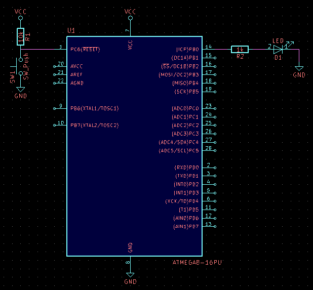
We need to build the circuit on a breadboard. This will be our schematic
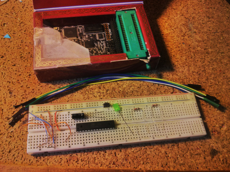
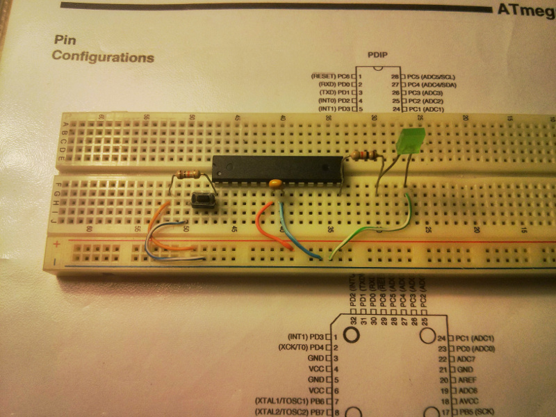
And that's how it looks like on a breaboard
If you've had contact with AVRs before, you will immediately know what each part is for. If not, let me quickly explain it. Starting from the left there is the 10k resistor. It takes care of keeping the micro running by keeping the /RESET pin in a logic HIGH state, which is at voltage VCC. Slash, or a line over the pin name means it's negated - it "does it's job" while it's in LOW state. The button is connected between the RESET pin and GND - when you push it, it will short the /RESET pin to ground, forcing a LOW state, and reset the microcontroller. The microcontroller will start to execute your program as soon as you release the button. The yellow bead is the capacitor. It keeps the electrical noise away from the insides of the micro. Continuing, we have another resistor - it's job is to limit the current flowing through the green LED to protect both the LED and the micro. Keep an eye on which way you insert the LED. Use a search engine to identify leads.
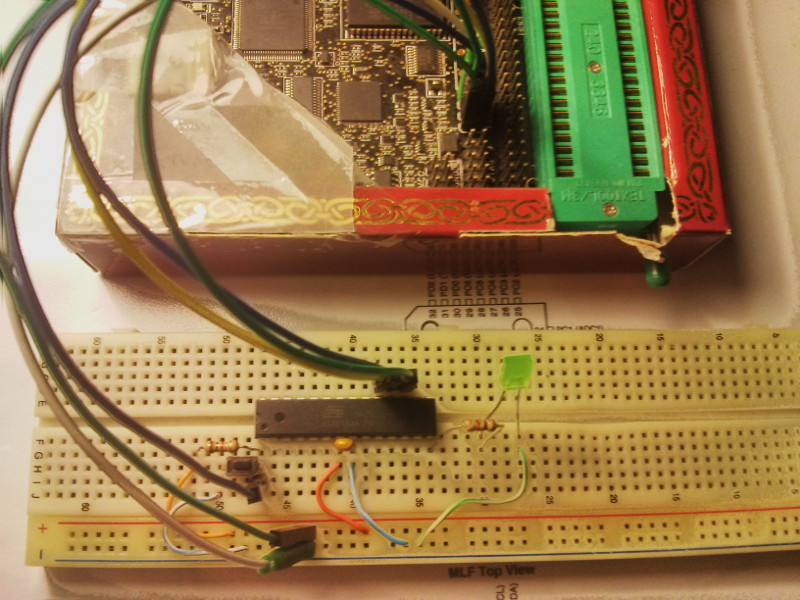
We will also connect the programmer to some of the pins of the AVR
MISO, MOSI, RST and SCK pins shold be connected to the micro. In case of atmega8 you can look the numbers on the schematic. The two power pins VCC (or sometimes VTG - abbreviation for Target Voltage) and GND should be connectd respectively to the positive voltage supply (VCC) and circuit ground (GND). If your programmer has the option to supply the power, you should enable it (unless you are powering the circuit from another source like a battery or a power supply!)
Let's run avrdude and see if it can talk to the chip. Enter the command (you may need to use sudo if avrdude can't access the USB device):
avrdude -p m8 -c [your programmer's name]You can search for the name of your programmer or put ? (a question mark) as the name - avrdude will then output a list of programmers and the respective values.
If you have wired everything correctly, you should see this message:
avrdude: AVR device initialized and ready to accept instructions

Reading | ################################################## | 100% 0.15s

avrdude: Device signature = 0x1e9307 (probably m8)

avrdude: safemode: Fuses OK (E:FF, H:D9, L:E1)

avrdude done.  Thank you.
Otherwise avrdude should tell you what's wrong (although in a way that may be cryptic to newcomers). For example a message like
avrdude: jtagmkII_setparm(): bad response to set parameter command: RSP_FAILED
avrdude: jtagmkII_getsync(): ISP activation failed, trying debugWire
avrdude: jtagmkII_setparm(): bad response to set parameter command: RSP_NO_TARGET_POWER
should be pretty self explanatory, RSP_NO_TARGET_POWER means the circuit is not powered :P
It's worth to mention that if you use the USBASP programmer (and 99% of people do, it looks like a pendrive with pins sticking out of it's "back"), avrdude may say
avrdude: warning: cannot set sck period. please check for usbasp firmware update.
avrdude: error: programm enable: target doesn't answer. 1
Again, the program tells you what's wrong. You need to update the firmware on your USBASP. I have never done this, since I had been using the paralell port homemade programmer (and then I bought a Dragon) but it's doable.
Now that you have the hardware part working, we can write the assembly program. Open your favourite text editor (on Linux, a graphical GEdit is fine, if you prefer text mode you can use nano, or, if you know how to, emacs or vim are great too) and a terminal, then create a new file somewhere on your PC. I suggest making a new directory for it because the compiler will output some files and it's nice to keep stuff organized.
Copy this code into the editor, save it as hello.S. All the source code can be found here
    #include <avr/io.h>

    .global main


    main:
    ldi r16, 0x01
    out  _SFR_IO_ADDR(DDRB), r16
    out _SFR_IO_ADDR(PORTB), r16

    loop:
    ;; delay loop
    ldi  r18, 6
    ldi  r19, 19
    ldi  r20, 174
    L1:
    dec  r20
    brne L1
    dec  r19
    brne L1
    dec  r18
    brne L1

    in r16, _SFR_IO_ADDR(PORTB)
    com r16
    out _SFR_IO_ADDR(PORTB), r16

    rjmp loop
Compile it with
avr-gcc -mmcu=atmega8 -o hello.elf hello.Sand make the output elf file into a HEX file that can be flashed with
avr-objcopy -j .text -j .data -O ihex hello.elf hello.hexThen flash it with
avrdude -p m8 -c [programmer name] -U flash:w:hello.hexOf course, use what you've used previously as the programmers name. After avrdude does it's job you should see the led blinking.
Before we begin analyzing this code, I should clarify some things. It's probably not similar to any programming language you already know. Assembly doesn't have variables, objects, structs, and many, many other things higher level languages have. All data transfer and operations is done on the CPU registers. The AVR has 32 of them, numbered from r0 to r31. Additionally the 3 highest pairs form the X, Y and Z 16-bit registers used by some 16-bit operations (like storing or retrieving data from the memory).
Some instructions also write to the Status Register (SREG) basing on their outcome. For example if a substraction result is zero, the Zero flag (Z) is written one. When a carry occurs (the result is "too big" to fit an 8 [or 16] bit register), the Carry flag (C) is set, etc.
Let's continue and analyze the code now.
We start by telling the preprocessor (remember we compile with avr-gcc!) that we want the io register definitons to be defined for us. This allows us to use PORTB, DDRB and other placeholders instead of writing their respective register adresses.
#include <avr/io.h>
Then we tell the compiler (or technically, the assembler) we want to write the main function (by standard the entry point of all programs. That's done by First we define a global label called main, so the linker will know that here is the entry point for our program. This is done by
    .global main

    main:
After the main label the program code starts. The first instruction is
ldi r16, 0x01
It stands for Load Immediate, and it loads a given constant to a given register. As you can see it loads 0x01 to register number 16 (r16). It's worth to mention that ldi can only load to the upper half of the register file (that is, r16 to r31). If you try to load to a lower register, the assembler will return an error.
We will use 0x01 in r16 in the next two instructions.
    out  _SFR_IO_ADDR(DDRB), r16
    out _SFR_IO_ADDR(PORTB), r16
The out instruction outputs a byte in a register to an I/O register. In our case it outputs the contents of r16 to DDRB, and PORTB.
We just did the equivalent of C's
DDRB = 0x01;
PORTB = 0x01;
in assembly. We loaded 0x01 into one CPU register and then used that CPU register to load 0x01 to two I/O registers. Notice that we use a macro _SFR_IO_ADDR(). That's because how registers are mapped in the micro's memory. You can access them as a part of RAM (using ST and LD instructions with their actual RAM adress, slower) or use IN and OUT instructions, using their I/O adress. It's explained pretty well in the datasheet. The definitions in avr/io.h provide the RAM adresses, so we need to use the macro to get the I/O adress. If you look at the datasheet you will notice that those two adresses are different by the same offset.
Now the loop part - we define a new label with
loop:and write a so called "delay loop"
    ;; delay loop
    ldi  r18, 6
    ldi  r19, 19
    ldi  r20, 174
L1:
    dec  r20
    brne L1
    dec  r19
    brne L1
    dec  r18
    brne L1
A delay loop is the easiest way to make a delay in assembly. It's a loop that runs for a calculated amount of time. In the instruction set in the datasheet,
there is given how much CPU cycles it takes. This one is programmed using dec and brne instructions. dec is the decrement instruction,
it substracts 1 from a given register. brne stands for Branch if Not Equal [zero] and it causes the program to go back to a given location (label) if
last operation has not set the Zero flag in SREG. In this case it jumps back as long as the previous decrement instruction resulted in a non zero outcome.
What happens when you try to decrement a register that is 0? It overflows back to 255. Then the decrement starts over.
Delay loop calculation can be pretty cumbersome so there are many online generators. It's out of scope of this tutorial to explain how it's calculated. Consult a search engine for details. This loop will wait 1 million cycles. On a 1MHz (factory default, not on arduino) CPU it's 1 second. AVRs taken out of arduino boards have fusebytes programmed in such a way they use an external 16MHz crystal for their clock. That loop would then wait, obviously 16 times shorter, 1/16 of a second.
Next part loads the PORTB register into r16, inverts it, and loads it back into PORTB. The in instruction is used to load from an I/O register to a CPU register. com is Ones Complement. It inverts all the bits in a given register. We had 0x01 in PORTB. We load 0x01 from it to r16. Then we invert the bits in r16 with com opcode - so now it's 0xFE. Next instruction, the out which you already know, puts 0xFE (contents of r16) to PORTB.
    in r16, _SFR_IO_ADDR(PORTB)
    com r16
    out _SFR_IO_ADDR(PORTB), r16

    ----------

    0x01 inverted gives 0xFE

    0x01 = 0b 0000 0001
           0b 1111 1110 = 0xFE
Last instruction
rjmp loop
makes the CPU go back to the place where loop label is defined. The delay loop gets executed again, PORTB get inverted, led changes it's state, over, and over again.
The full listing of all opcodes is in every datasheet, it's one of the chapters on in the end.
Now that you have made your first assembly program, it's time to make another one. You can make a program that copies the input from one port to the output of another port, or you can use two halves of the same port.
In theory we could have used avr-as, the assembler, to compile out assembly program. It would create a file that has nothing but the code we have written. And if we flashed it, it would have worked. So why did we use avr-gcc, the C compiler in the first place?
Let's take a look at what avr-gcc outputs when it compiles your C program.
Binutils for AVR have a tool called avr-objdump, a version of objdump for the AVR architecture. Let's use it to decompile a simple C program
    File: decompile.c

#define F_CPU 1000000L
#include <avr/io.h>
#include <util/delay.h>

int main(){
    DDRB = 0xFF;
    PORTB = 0x01;
    while(1){
	PORTB++;
	_delay_ms(100);
    }
}
Compile with (-g enables debug information)
avr-gcc -mmcu=atmega8 -Os -g decompile.c -o decompileNow we can use avr-objdump to decompile and take a look at the output assembly
$ avr-objdump -dS decompile

decompile:     file format elf32-avr


Disassembly of section .text:

00000000 <__vectors>:
   0:	12 c0       	rjmp	.+36     	; 0x26 <__ctors_end>
   2:	19 c0       	rjmp	.+50     	; 0x36 <__bad_interrupt>
   4:	18 c0       	rjmp	.+48     	; 0x36 <__bad_interrupt>
   6:	17 c0       	rjmp	.+46     	; 0x36 <__bad_interrupt>
   8:	16 c0       	rjmp	.+44     	; 0x36 <__bad_interrupt>
   a:	15 c0       	rjmp	.+42     	; 0x36 <__bad_interrupt>
   c:	14 c0       	rjmp	.+40     	; 0x36 <__bad_interrupt>
   e:	13 c0       	rjmp	.+38     	; 0x36 <__bad_interrupt>
  10:	12 c0       	rjmp	.+36     	; 0x36 <__bad_interrupt>
  12:	11 c0       	rjmp	.+34     	; 0x36 <__bad_interrupt>
  14:	10 c0       	rjmp	.+32     	; 0x36 <__bad_interrupt>
  16:	0f c0       	rjmp	.+30     	; 0x36 <__bad_interrupt>
  18:	0e c0       	rjmp	.+28     	; 0x36 <__bad_interrupt>
  1a:	0d c0       	rjmp	.+26     	; 0x36 <__bad_interrupt>
  1c:	0c c0       	rjmp	.+24     	; 0x36 <__bad_interrupt>
  1e:	0b c0       	rjmp	.+22     	; 0x36 <__bad_interrupt>
  20:	0a c0       	rjmp	.+20     	; 0x36 <__bad_interrupt>
  22:	09 c0       	rjmp	.+18     	; 0x36 <__bad_interrupt>
  24:	08 c0       	rjmp	.+16     	; 0x36 <__bad_interrupt>

00000026 <__ctors_end>:
  26:	11 24       	eor	r1, r1
  28:	1f be       	out	0x3f, r1	; 63
  2a:	cf e5       	ldi	r28, 0x5F	; 95
  2c:	d4 e0       	ldi	r29, 0x04	; 4
  2e:	de bf       	out	0x3e, r29	; 62
  30:	cd bf       	out	0x3d, r28	; 61
  32:	02 d0       	rcall	.+4      	; 0x38 <main>
  34:	0f c0       	rjmp	.+30     	; 0x54 <_exit>

00000036 <__bad_interrupt>:
  36:	e4 cf       	rjmp	.-56     	; 0x0 <__vectors>

00000038 <main>:
#define F_CPU 1000000L
#include <avr/io.h>
#include <util/delay.h>

int main(){
  DDRB = 0xFF;
  38:	8f ef       	ldi	r24, 0xFF	; 255
  3a:	87 bb       	out	0x17, r24	; 23
  PORTB = 0x01;
  3c:	81 e0       	ldi	r24, 0x01	; 1
  3e:	88 bb       	out	0x18, r24	; 24
  while(1){
    PORTB++;
  40:	88 b3       	in	r24, 0x18	; 24
  42:	8f 5f       	subi	r24, 0xFF	; 255
  44:	88 bb       	out	0x18, r24	; 24
	#else
		//round up by default
		__ticks_dc = (uint32_t)(ceil(fabs(__tmp)));
	#endif

	__builtin_avr_delay_cycles(__ticks_dc);
  46:	87 ea       	ldi	r24, 0xA7	; 167
  48:	91 e6       	ldi	r25, 0x61	; 97
  4a:	01 97       	sbiw	r24, 0x01	; 1
  4c:	f1 f7       	brne	.-4      	; 0x4a <__SREG__+0xb>
  4e:	00 c0       	rjmp	.+0      	; 0x50 <__SREG__+0x11>
  50:	00 00       	nop
  52:	f6 cf       	rjmp	.-20     	; 0x40 <__SREG__+0x1>

00000054 <_exit>:
  54:	f8 94       	cli

00000056 <__stop_program>:
  56:	ff cf       	rjmp	.-2      	; 0x56 <__stop_program>
Note: You can also use -S option of GCC to output generated assembly. It's more conveinient in bigger programs but in this case I wanted to show the whole listing
Also, take a look how the C's _delay_ms() macro is constructed. Instead of nesting two 8-bit loops, it decrements (using sbiw - Substract immediate word, substract a constant from a 16-bit value in a register pair).
When the CPU powers on, it starts execution of the program from adress 0. The first instruction is a jump to label __ctors_end. The CPU must do this, because after the first operand (opcodes are 2 bytes long) at adress 2, lays the interrupt table which contains the interrupt vectors. In this case, all of them jump to __bad_interrupt because no ISR is defined in out program. If we defined an ISR, one of those vectors would become a jump to the newly defined subroutine (it's a method equivalent in assembly). This is why if you enable an interrupt and forget to define an ISR() for it, the CPU will soft-reset when that interrupt occurs, because __bad_interrupt jumps to __vectors which is adress 0). You can read more about the interrupt handling in the datasheet.
__ctors_end takes care of initializing the stack pointer - that's necesary for the stack to work. The main is pretty self-explanatory.
In theory we could use the assembler, avr-as to write the interrupt table, the stack initialization code and (not included by the compiler here) the code that initializes variables. But we may as well save ourselves the hassle as the C compiler (or technically the linked invoked by it) generates all this stuff for us. We also get to use predefined macros from avr/io.h, otherwise we would have to use assembler directives like .equ (similar to #define)
Instead of typing all the commands every time, why not use the good ol' makefile? Here's how it can look like
all: compile flash

compile:
	avr-gcc -mmcu=atmega8 -o hello.elf hello.S
	avr-objcopy -j .text -j .data -O ihex hello.elf hello.hex
flash:
	avrdude -p m8 -c dragon_isp -U flash:w:hello.hex
clean:
	rm hello.elf hello.hex
That's all! Hope you enjoyed this tutorial, stay tuned for another parts!