Back to homepage2020-04-04
This is a linear actuator I've built recently. It's a cool project, because I have never built a servomechanism before. I knew how to drive steppers already, but the challenging part was to add a feedback loop so that the CPU is aware of the head position, instead of blindly turning the motor back and forth.
I chose a linear actuator because I think it's a very useful part. This one will probably not be used except for development and testing, but I've learnt a good deal of useful stuff on it already.
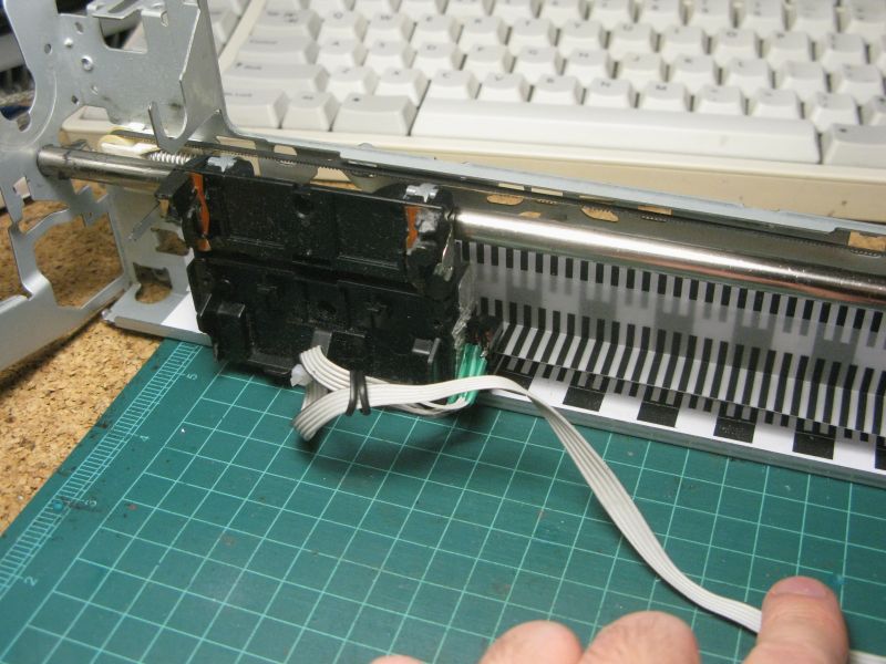
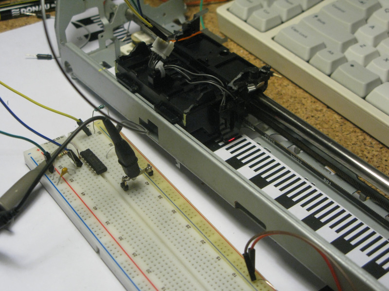
The whole thing is built on a printer head assembly chassis. From the original assembly, only the shaft, belt and the head parts were left. The stepper motor was retrofitted from another printer (this chassis used a regualr DC motor originally)
I've done some experiments with photointerruptors. At first I wanted to use this nice reflective one, with a LED and a phototransistor. But it turned out that for the LED currents acceptable (100mA was very much over the limit of what I comfortably wanted to pump thru a LED that size), the only sensible photocurrent resistors were in the range of 1Mohm. Even worse, it seemed to to be extremely sensitive to external light. That just would not cut it.
I've tried adding a small shade to it, but in the end I went for a semitranslucent encoder strip and a photointerruptor.
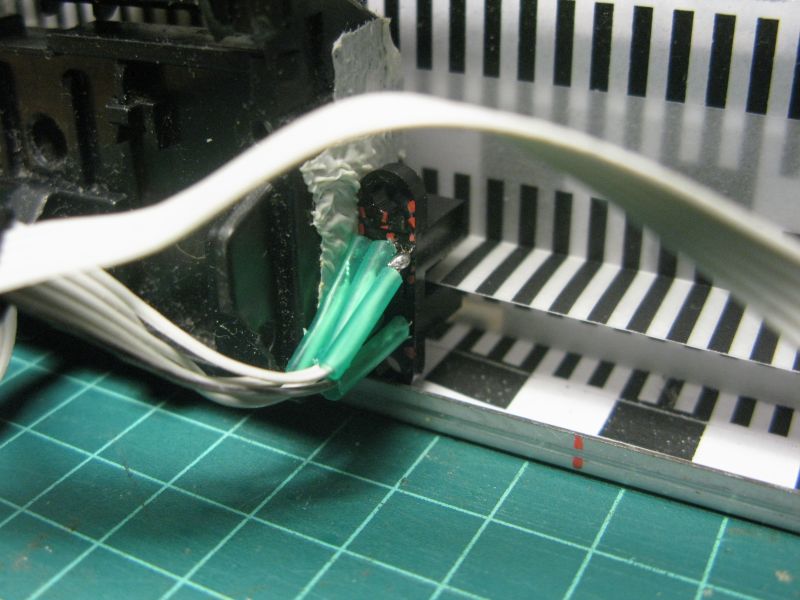
The encoder strip was made as an SVG of 2-mm wide black and white (transparent) stripes. I printed it on tracing paper. I've also added a thin, straight line through the middle of the strip to facilitate priming and bending it correctly
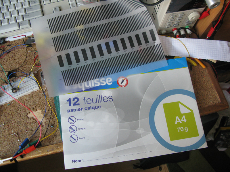
This paper is pretty good for printouts. I've used it in several projects.
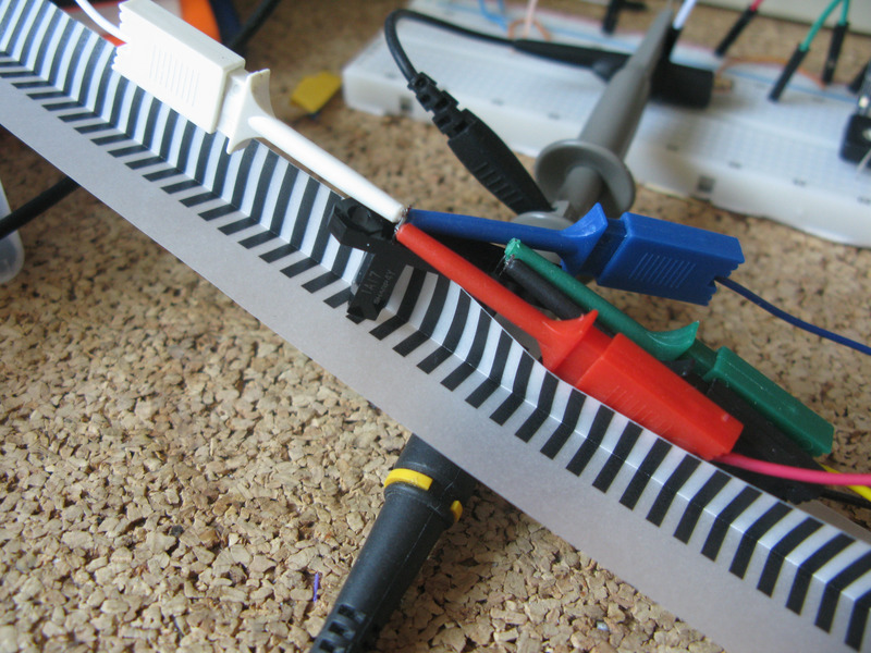
The initial testing to pick the right LED current/resistor for the photointerruptor. The double opaque layer makes it a bit high, but not as high as it would have to be with the reflective kind of detector
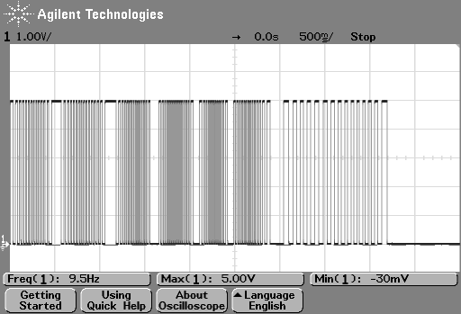
The signal it generates is also very sharp, and pretty much ready to feed to a digital input. The signal below is what it generates if you move the encoder strip back and forth
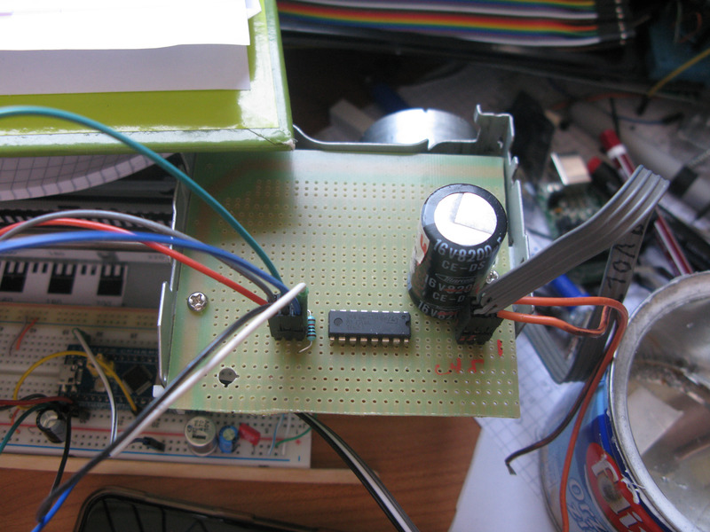
The controller for the whole thing is an STM32F103 on a well known bluepill module. The photointerruptor signal is connected to an external interrupt (EXTI) pin. The service routine counts the pulses up or down based on the current motor direction (the direction is not sensed in this version, I'm planning to add that in the next build maybe).
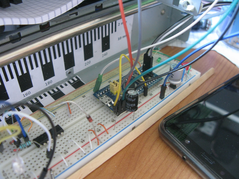
That data is then used to control an L239D dual H-bridge that drives a stepper in bipolar mode. The stepper driver was getting a little warm so I've attached a heat sink to it later.