polprog 25.09.2021
Guide to aligning the read heads of floppy drives.
You will need:
Symptoms of misaligned floppy disk head are easy to spot. If the drive is unable to read disks which other drives read correctly, it might have a head alignment issue. A definitive symptom is that a disk formatted in the drive reads fine only in that drive, and fails to read in other drives.
Before attempting to realign the heads you should try to clean them with isopropanol and a cotton bud (unless the latter symptom occurs)
Another use of this tecnique can be to purposedly misalign the drive heads against a misaligned floppy disk, to read data from a floppy that was formatted in a misaligned drive and cannot be read in a correctly aligned drive.
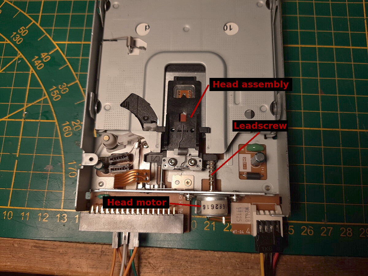
The head mechanism: Stepper motor, leadscrew and head assembly
The head is actuated by the smaller stepper motor. The leadscrew is designed so that one step of the motor moves the head by one track's pitch, about 200um (0.2mm). Head misalignment happens when the steps do not land the head over the tracks, but in between them
The idea behind aligning the drive is simple. You have to adjust the position of the head stepper motor so that when it steps, the head falls on the track of the magnetic disk. You can rotate the head stepper motor by loosening the two screws that hold it to the chassis, they are designed so that they can be rotated to the right position and then fastened by tightening these screws. Often there can be some threadlocker applied to them to stop them from loosening (and losing head alignment)
Open the floppy drive to access the controller PCB. There should be two head signal test points. On my drive, they are labeled "A" and "B". These are test outputs from the sense amplifier in the floppy drive controller.
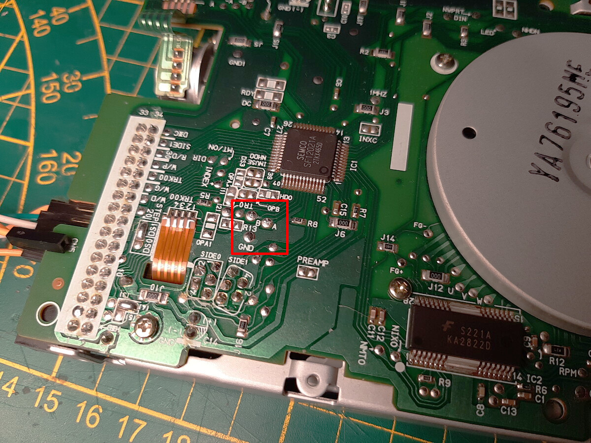
"A" and "B" test points near the disk controller IC
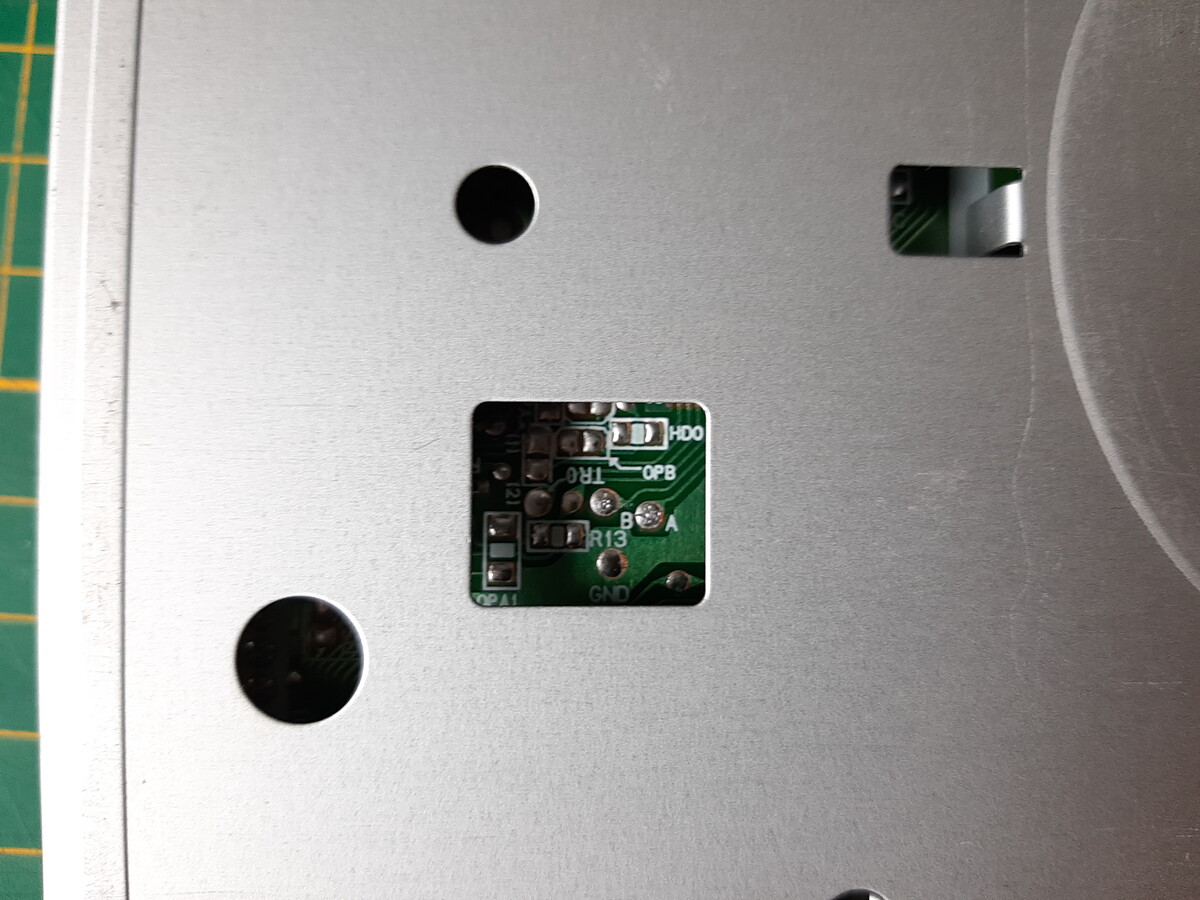
Sometimes the test points may be accessible without taking the drive chassis apart.
Using jumpers or jumper wires, jump the following pins on the floppy drive header
Pin 1 is bottom left of the connector (looking at the rear of the drive, connector key facing down)
Connect the ground clip of your scope probe to the ground on the floppy disk. Most likely it will be some exposed metal of the chassis, but confirm that with a multimeter. Note that if you are powering the drive from an ATX power supply, then the supply ground and the oscilloscope ground is connected to PE and if you touch the scope ground to a non-ground on the PCB you will cause a short. The floppy disk drive is not a floating system!
Now you can connect the power from the ATX power supply to the drive. Start the ATX supply by shorting the green wire of the 20/24 pin connector to ground. The activity led should light up and the disk drive should start spinning. The head should also start stepping. If you hear the head hit either end of the drive, disconnect or reconnect the jumper wire on pin 18 (Direction select).
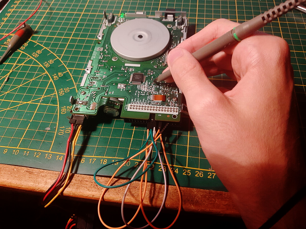
Probing the head signal test points
You can now start probing the test points for the head signal Set your scope to AC coupling, 100mV/div, 5ms/div. Touch one of the test points with the probe tip. Note that the read heads are current, not voltage signals and you will not see them when probing the head connectors directly. You need to use the test output from the drive controller.
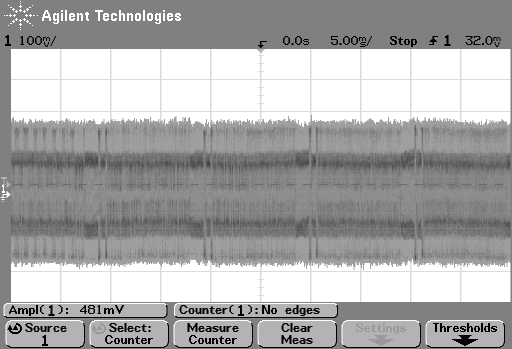
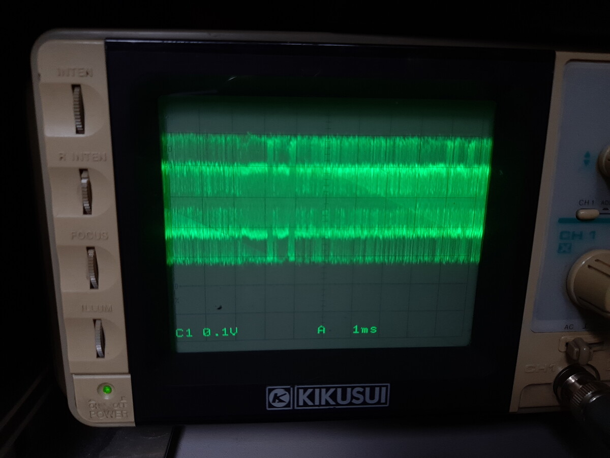
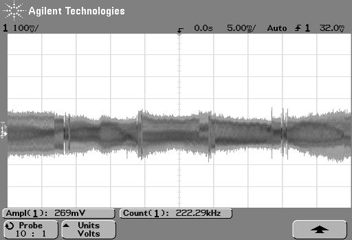
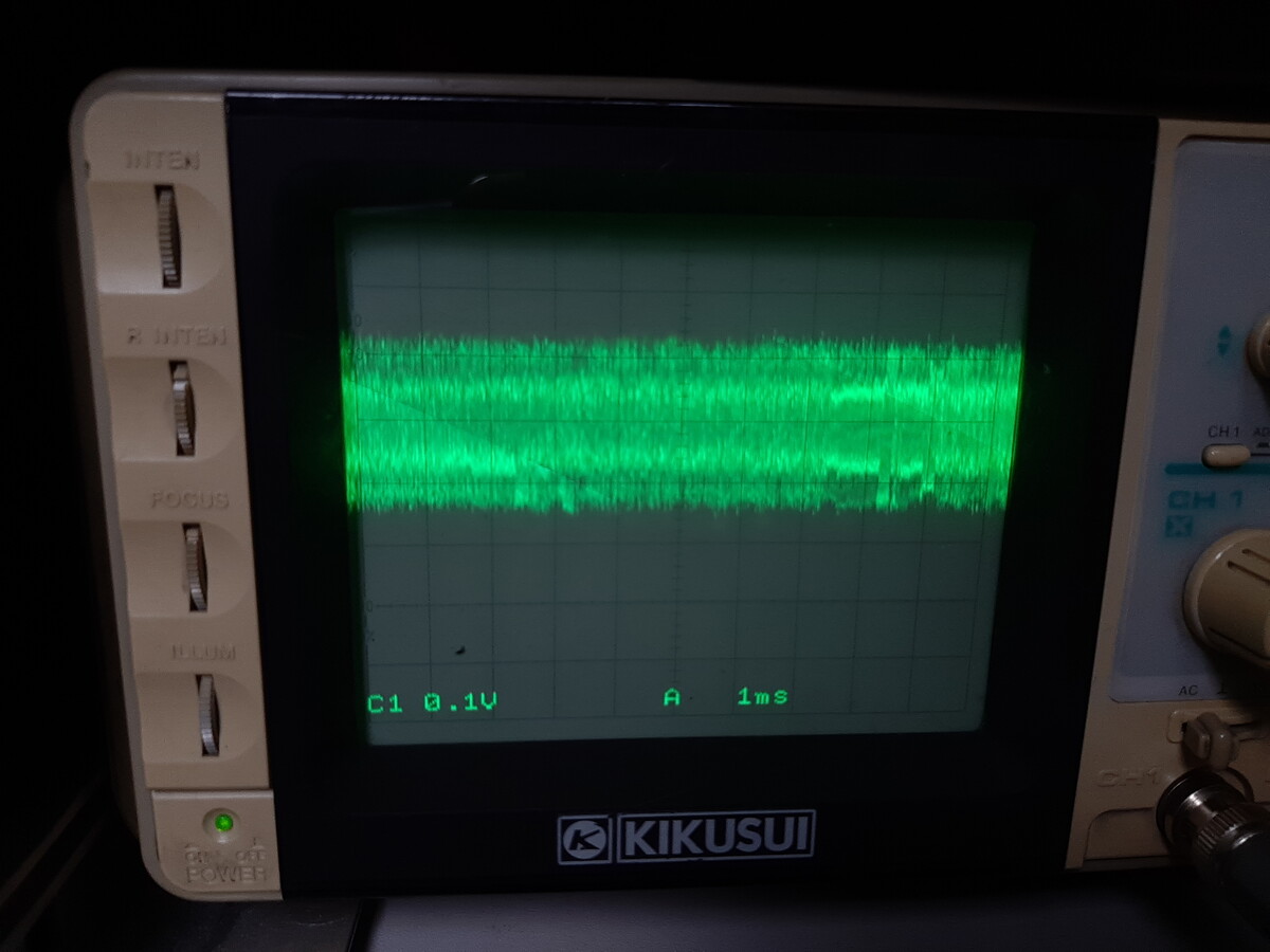
There should be a test point with a signal similar to one of those below. I'm showing signals as seen on a digital and analog oscilloscope.
Correct head signals. A two level signal is clearly visible. Do not touch the head motor alignment!
Misaligned head signal: Amplitude is low and not steady. If the read head signal is like in these images, you have to realign the head stepper motor.
When you find the signal, change the sweep time of your oscilloscope to 1us/div to see the eye pattern. An analog or a high quality digital oscilloscope is best for that.
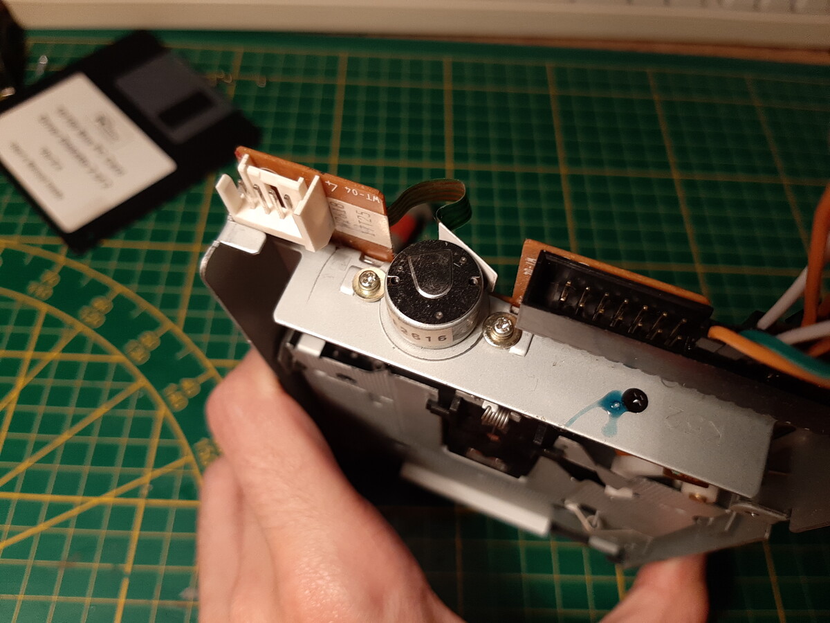
The head stepper motor and two screws fastening it in place
While the disk is spinning, watch the eye pattern showing on the oscilloscope. Align the head by turning the motor body either way, so that the openings are wide and the amplitude is at maximum. Then fasten the head screws back. Remember to change the step direction if you hear the head hit the limit. Ideally, the amplitude should be uniform across all the tracks (for any head position)
If you have a digital oscilloscope, set your trigger to trigger on both edges to get a clear eye pattern image.
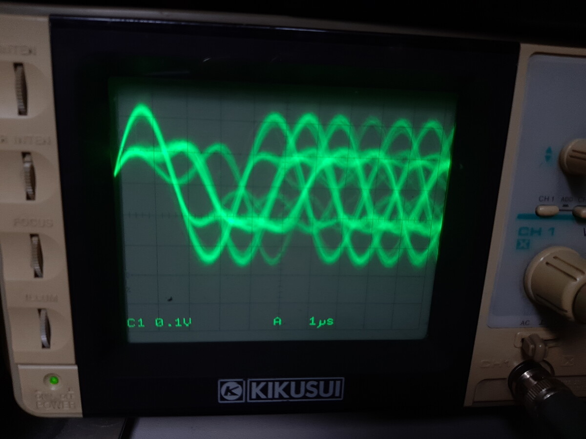
Correct eye pattern. Large amplitude and clear openings
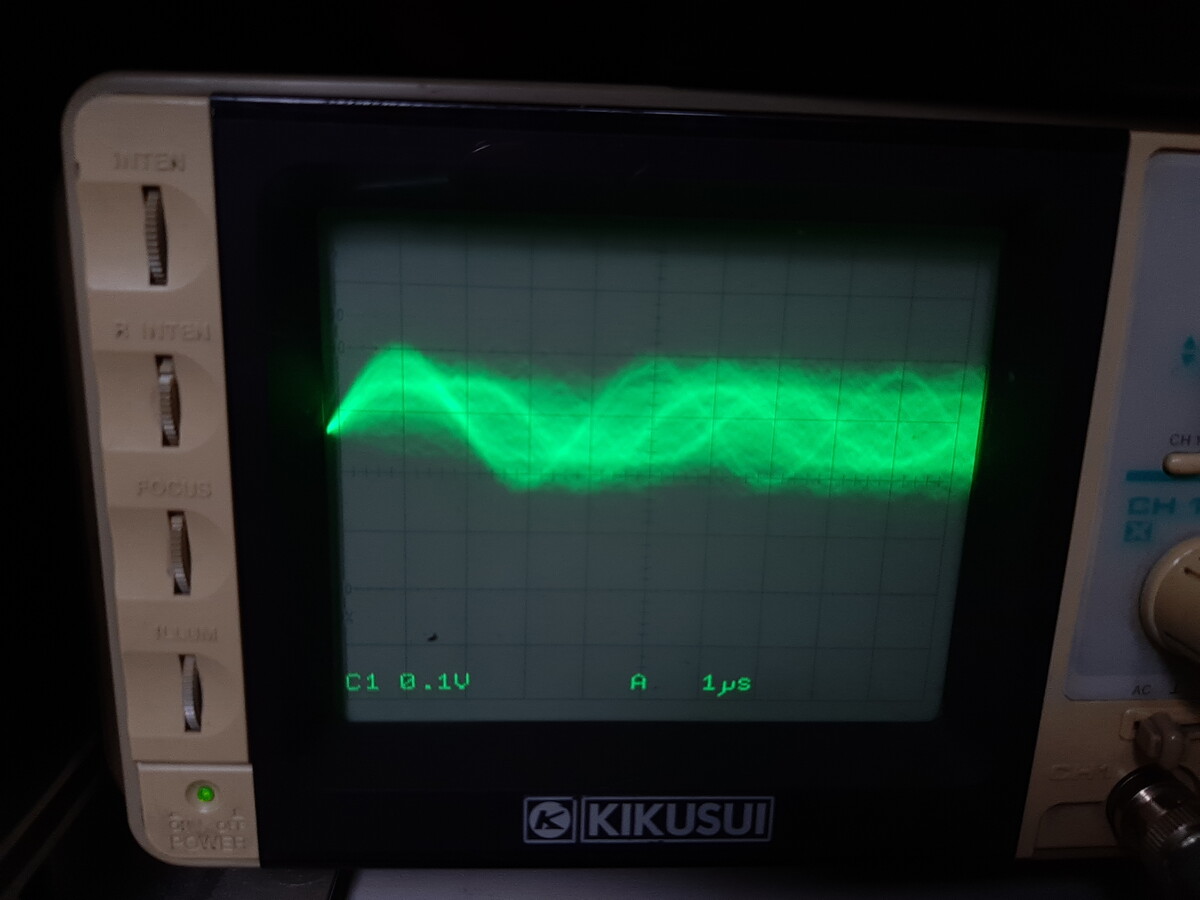
Weak signal - no eye pattern at all
Verify if the floppy drive works in a system, for example by booting it, or reading several known good disks. Look for read errors.
We align the head so that steps of the head motor will land the head entirely over the track area. If the head is only partially over the track, the magnetic fluctuations of the medium will induce a smaller signal in the head causing a weaker and uneven signal. We monitor the signal while aligning the drive and try to make it as strong as possible. In order for the head signal to apear, the disk must be spinning. This is done by asserting the DRVSB# and MOTEB# signals on the header (pins 12 and 10).
However, we also need to energize the head stepper motor while aligning it. Otherwise turning the stepper motor will only turn it's body, while the shaft stays held by the head assembly. Stepping it repeatedly is achieved by jumping the STEP# signal (pin 20) to INDEX# signal (pin 8). The index signal is generated by the drive when the floppy disk medium is in the index position. While the disk is spinning, there is a pulse train appearing on that pin and we use that pulse train to step the head. The head is stepping relatively often, so if you rotate the motor slowly then the effect of turning just the body is minimized. By using the INDEX# signal we also make sure that the head reads the entire length of the track before stepping to another, which allows us to align it with the entire track.
Finally, you have to reconnect and disconnect the DIR# pin every now and then to avoid the head hitting the disk ends.
By default and for historic reasons, PC floppy drives are configured as Drive 1, and having two drives on the same FDC is possible due to cable twist. If you have a floppy drive that is configured as Drive 0 (as is the case for example, in an Amiga), then you have to use DRVSA# and MOTEA# sigals.
A PC compatible floppy disk rotates 5 times per second. With a typical 1440KB format (18 sect/track, 80 tracks) that gives us about 11ms per sector. You can see the sector headers in the digital scope screenshot showing the correct head alignment.
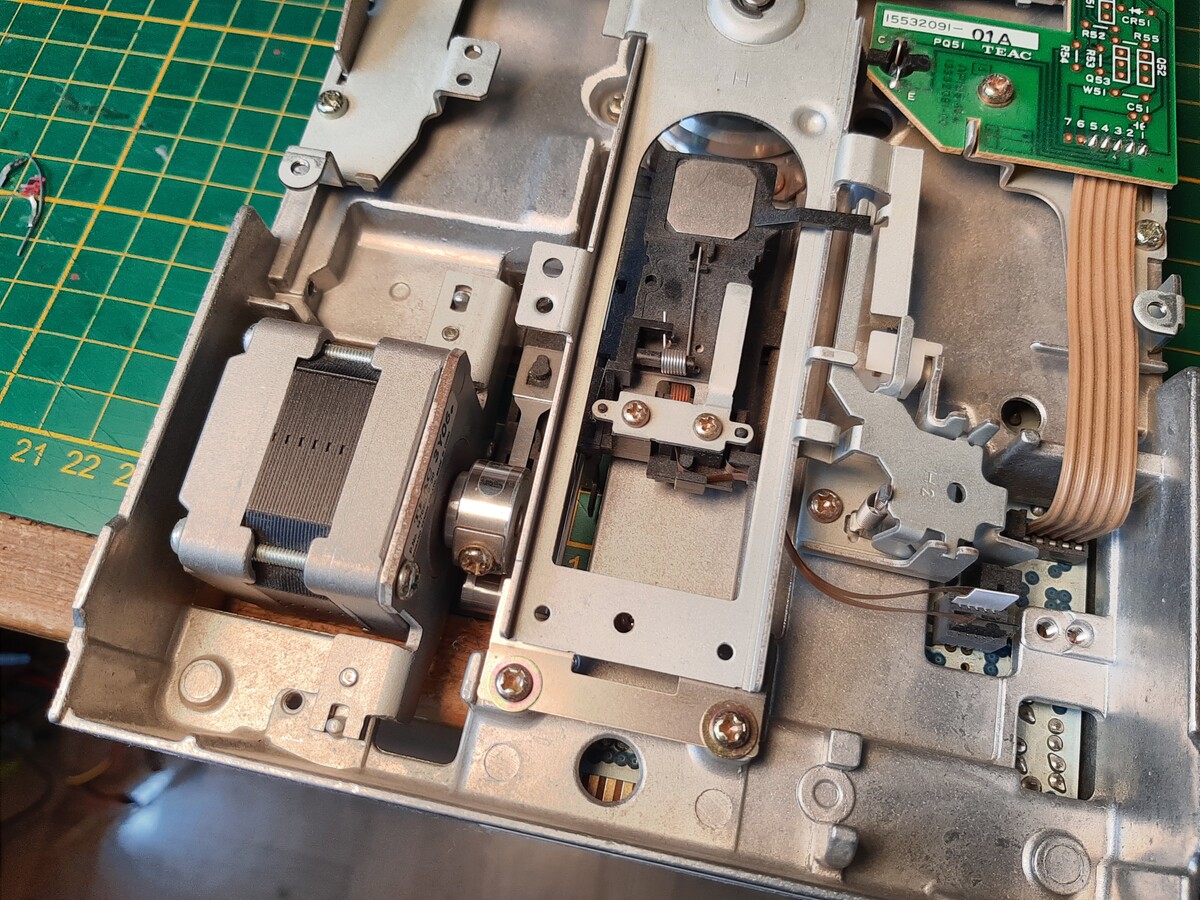
The head mechanism of a 5.25" drive. Stepper motor, tape linkage, head assembly.
A similar approach can be used for 5.25" drives, here the head actuation mechanism is different. These stepper motors are somewhat easier to align as the shaft takes some force to rotate. In 5.25" drives you should just need to make the disk spin, loosen the screw on the stepper motor head and align the head manually, then tighten the screw. You might need another person to hold the scope probe, as it takes 3 hands to do it all at the same time.
The eye pattern might look different as these use a different medium encoding (they may use FM or GCR encoding, while most 3.5" drives are PC compatibles and use MFM encoding)
Back to home page