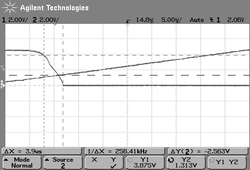
 The ramp going up is the input voltage, the other trace is the output voltage. Vcc = 5V
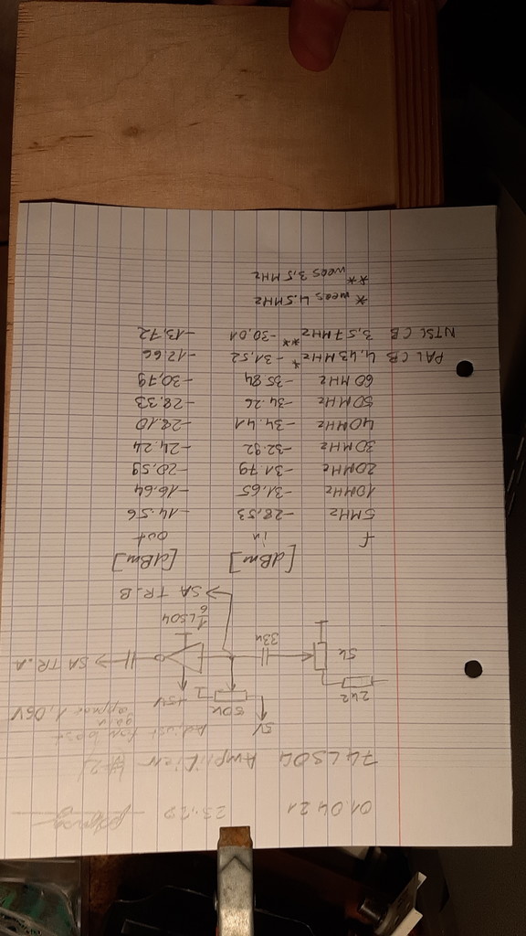
01.04.21 polprog (but this is for realz!)
74LS04 and some other 74xx04 inverters have a linear region where they behave like an inverting amplifier. This means that if you feed it a signal somewhere in the middle of the logic level thresholds it will output an "invalid" logic level...
For a range of voltages it behaves like an inverting amplifier.
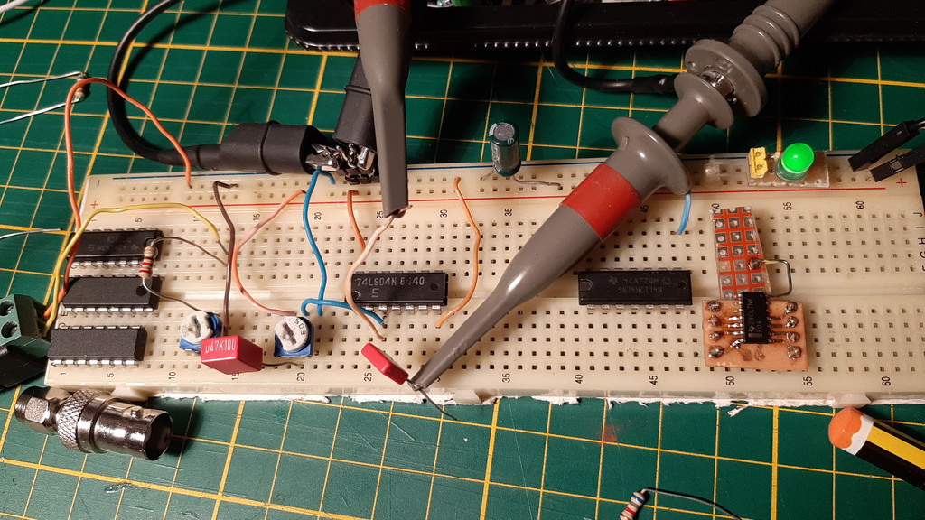
You can conenct a potentiometer voltage divider or a triangle wave gen to the input
and watch the output voltage. There will be a range of input voltages where the ampli..
uhh.. I mean inverter will operate in a linear region:
The ramp going up is the input voltage, the other trace is the output voltage. Vcc = 5V
74x04 linear regions @Vcc=5V
----------------------------
part        range
74LS04    1.3V - 3.8V
74F04     1.5V - 4.0V
74AC04    no linear region
74HCT04   no linear region
This means that if you feed it a properly biased (here done by the 50k pot) small signal, you will get an amplified signal on the output
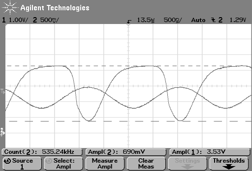
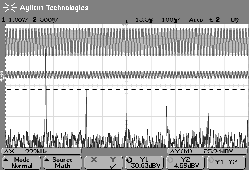
It does distort the signal a little, in here a sine wave from a generator is fed to the inpit and the output is visibly distorted. But if the input level and bias are set correctly then the second harmonic will be at about 25dB lower than the primary. Additionally the distortion seems to be smaller when I feed it a smaller signal, but I have to check that yet. The input sine from the gen can be regared as pure sine (I checked it on the FFT) so the FFT measurement of the output shows the distortion pretty clearly.
If you are targeting to buffer a specific frequency then you should be good to clean the output up with a bandpass filter making it a class F-like amplifier
For these small signals you can imagine that inside is an inverting opamp with the + input fixed to some voltage at about where the input and output traces intercept (which works out to about just above the low level threshold (for 74LS04 bias at 1.0-ish V)
This circuit is running in open loop so it has a frequency slope. I have to experiment with closed loop gain in the future.
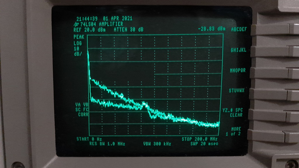
Here's two spectrum analyzer traces. Top trace is output, bottom is input. I connected my noise source to the input as I dont have a tracking gen.
A rough look at the SA trace would indicate that the GBP of the 74LS04 is about 80MHz. (this is all on a breadboard)
I have yet to experiment. Closed loop gain, maybe even filters tbd. I should also test the performance of the 74F04, 74HC04,( and sn74lvc1gu04 if I remember to buy some)
4000 series - 4009 (inverter) 4010 (buffer), datasheet from TI has internal schematics.
74xx06 - open collector inverter? maybe that could bring some good results if the feedback loop works out