12.11.2023 polprog
I am collecting computers for a while now. Specifically, single board computers - the weirder system, architecture or CPU that runs it, the better. I love to study how they are designed and how they work. My aim with them is to boot Linux (or any other operating system) completely from scratch. I wanted to understand exactly how, from the moment of power up, the computer arrives at a shell prompt.
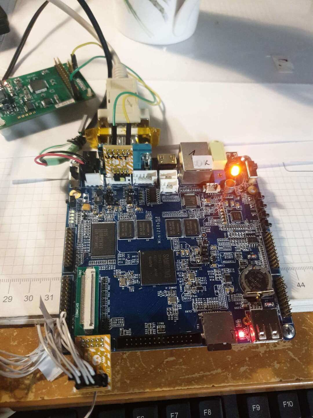
One of the recent finds was mini210, a Samsung S5PV210-based SBC from FriendlyARM. I found someone selling two of them for 25PLN (US $6) each, and that's how I got my hands on them. Later I realized that this was a very good deal, as new ones are being currently sold for US $139 (whether an old armv7 is worth anything at all, is a separate thing).
And I thought - I will try to make this computer do something useful. Let's say, become a node in a sensor network. Of course I could buy a ready made thing - but where is the fun in that?
The first step in booting Linux is the bootloader. I found manufacturers bootloader to be lacking features. So I ported U-Boot to this board. This text goes into technical details of how I troubleshoot this board to finally get U-Boot running, and how the early boot process of U-Boot works.
I did a bit of gooling before buying them, and I found that S5PV210 is reasonably well supported in Linux kernel. I decided to go for it, buying both SBCs from the previous owner. Booting Linux from a complete scratch, on a non-x86 system, has been my goal for a few years now. This is why I decided to give it a try.
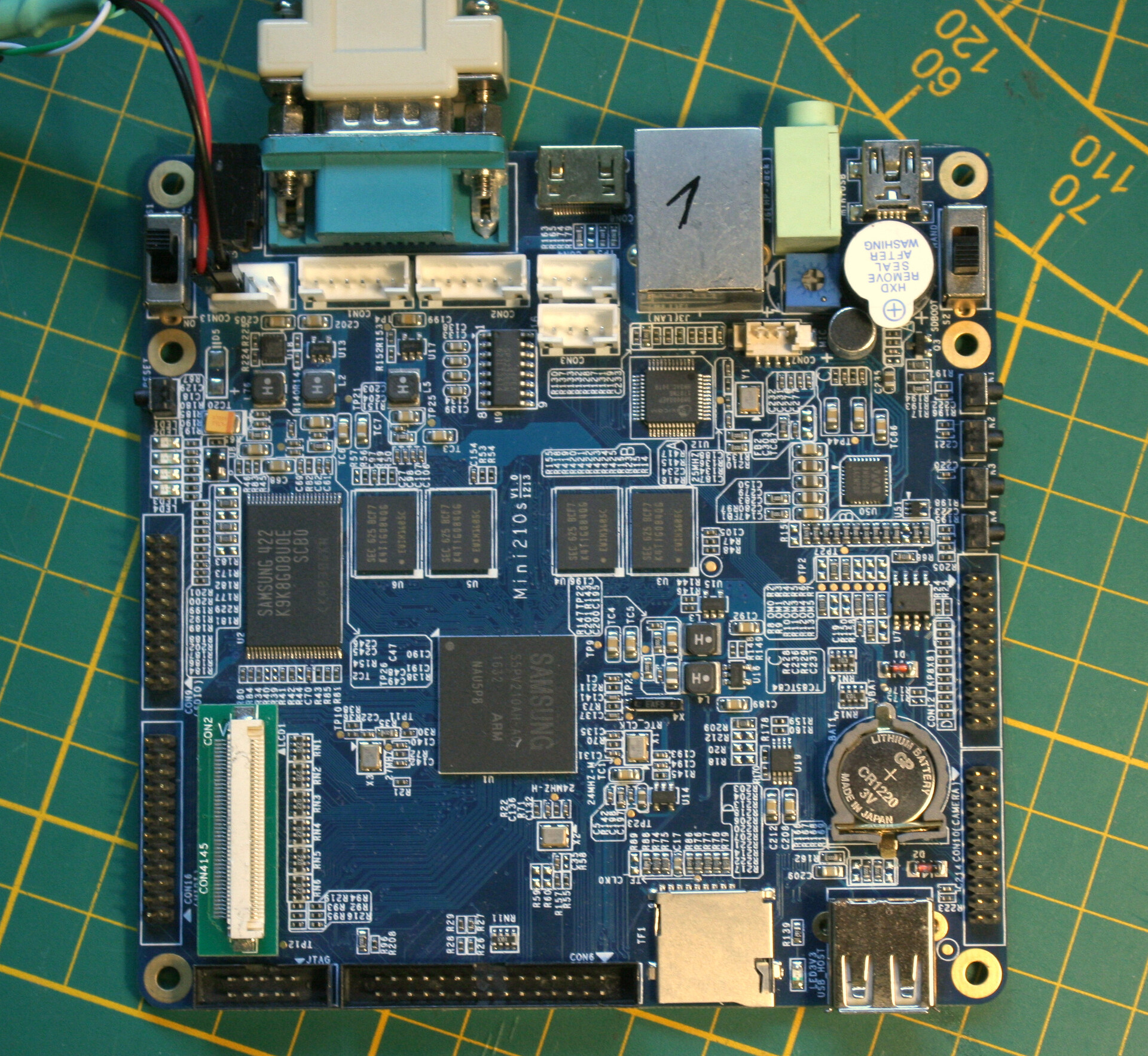
S5PV210 is a low power ARM Cortex-A8 microprocessor targeted at mobile phones. It was released in 2009 as "Industry's first 1.0GHz mobile processor" and powered devices like the original Samsung Galaxy Tab.
mini210 is a small single board computer centered around the S5PV210, designed to build embedded systems. Almost instantly I found FriendlyARM's distribution DVDs, which contain resources to run Android 4.0.3, Linux 3.0.8 and, of all other things, Windows CE6.
After the package arrived I confirmed that they work and put them aside. My goal was to run a reasonably modern Linux on them, but first I wanted to see if I could find anything that would make this easier. The manufacturer's DVD came with a lot of examples for bare metal development on the CPU, as well as images of the three OSes mentioned above and respective source code. At that point the three most useful resources on the DVD were:
I've installed the compiler and spent a while reading the application note and trying to get the LEDs example working. This is an important step - blinking the LED is the simplest thing you can program, and it confirms that all the basic cogs of a complicated machine this CPU is, are working. In particular, it tells you the following:
If any of these steps fails, there really is no point trying to run anything more complicated. Additionally, once the LED blink program is running you can connect to it with a debugger and be able to peek at the memory values and control the execution manually.
At the end of that day I had one of the mini210s blinking it's 4 LEDs. A small success - I could compile code (at least assembly), move it to the SD card and run it with the embedded boot ROM.
I was quite happy with that success. I found a computer which was not expensive and (for me) quite interesting. With a bit of work I can make it usable again. I think this is a good thing, even if it ends up running something as basic as a webserver serving some static page...
This was a good start, but my aim was to run U-Boot on the board. The manufacturer provides Superboot, a different bootloader that is used to bootstrap the Linux and Android demo images, but after reading it's documentation I found it a bit too basic for my taste.
U-Boot on the other hand, is a de-facto standard bootloader on ARM today, which makes it conveinient to use. It's easier to work with a known bootloader, and because it's open source, I can modify it to my needs. U-Boot also has way more features than Superboot - interactive console, support for USB and network booting are one of the most useful for embedded development. Eventually I got U-Boot working on this board, and posted my fork to github. Perhaps you are reading this text because you also have one of these computers, and like me, would like to make use of it.
For that reason, soon after I got the leds example working, I focused my internet searches on anything related to S5PV210 CPU programming. Standing on the shoulders of giants, and all that.
I found several useful resources regarding the CPU:
Documentation/arch/arm/samsung/overview.rst or hereas well as several forks of U-Boot from various years:
I also found a yocto layer for the CPU, which looks like it's related to porting something to Galaxy S devices: meta-s5pv210 yocto layer and u-boot fork that it uses.
Once you apply power to the CPU, it starts a bootup process. Usually the first stage of that process is to run fixed code from a boot ROM. The boot ROM (called iROM in Samsung's documentation) on this CPU is particularly nice and easy to work with. S5PV210 supports booting from several different media including different types of NAND, and the boot option is selected using 6 option pins called OM[0:5]. The mini210 straps them with resistors and then uses a switch and a single IC logic gate to switch two of these pins between booting from the internal NAND and SD card.
The boot sequence is typical and uses three stages, each stage is more complex and larger than the previous one. Samsung calls these stages BL0, BL1 and BL2, this is their idea of which stage does what tasks:
BL0 is the smallest boot stage. It is stored in the ROM inside the CPU, so it cannot be altered or updated. It needs to be error proof, so it's functionality is kept to a bare minimum.
However, both BL1 and BL2 are provided by the user on the boot medium, so what they do is up to your imagination. U-Boot in particular does things a bit differently than the Samsung app note suggests, but let's not get ahead of ourselves.
The led blink example had a tool that lets you prepare an SD card so that iROM recognizes it as bootable. iROM needs the boot binary file on the SD card to reside in the first (not zeroth) block and have a 16 byte header that tells it the size of the binary and the checksum. Optionally, if Secure Boot is enabled, it can have a cryptographic signature that goes after the binary.
The iROM has a very minimalistic error reporting feature - if it fails, the resason is "displayed" as a PWM waveform on one of the GPIO pins. The duty cycle of the waveform indicates the fault condition. On the mini210 that pin is connected to the onboard beeper. So at that point, iROM troubleshooting is done using an oscilloscope to measure that duty cycle and then look up the error code in a table.
Fun fact: as of time of this writing I stil did not modify U-Boot so that it sets the logic level on that pin to turn off the beeper. During development I simply replaced the beeper with a LED :)
Flashing LEDs using a ready made example from the board manufacturer is a straightforward task. The example is made so that it will work as long as you have the right compiler (which is also given). However, in order to develop more complicated programs, it's necesary to be able to look at the machine state when they inevitably crash. In these CPUs there are so many moving parts that its not possible to fix problems by guessing.
This is where JTAG comes in to play. JTAG on it's own does not provide any debug capabilities - it only gives you a way to transfer data between your computer and the target device (the chip). Debugging is done by CoreSight, a standardized way of connecting parts of ARM cores together. In most ARM CPUs out there, CoreSight exposes a Debug Access Port, or DAP. The DAP lets you control the code execution and modify memory and registers in the CPU. JTAG is used to move data to and from the DAP.
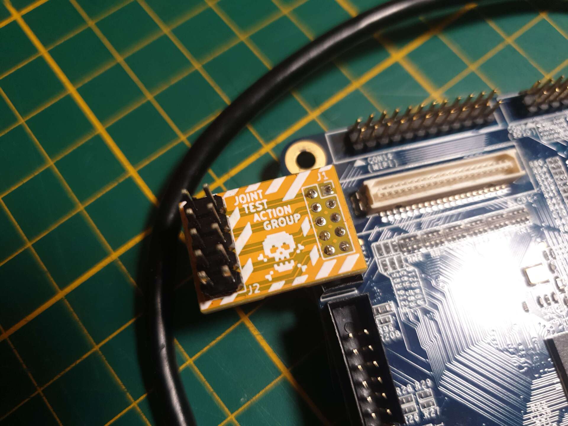
The mini210 uses 2.00mm pitch pins for almost everything including JTAG. This is a problem because 2.54mm pitch headers are more common, and this was the pitch of my JTAG adapter connector. I've quickly bought some 2.00mm headers and designed a 2.54mm to 2.00mm adapter board. Since it had some space, I decided to put some funky graphics on the silkscreen layer!
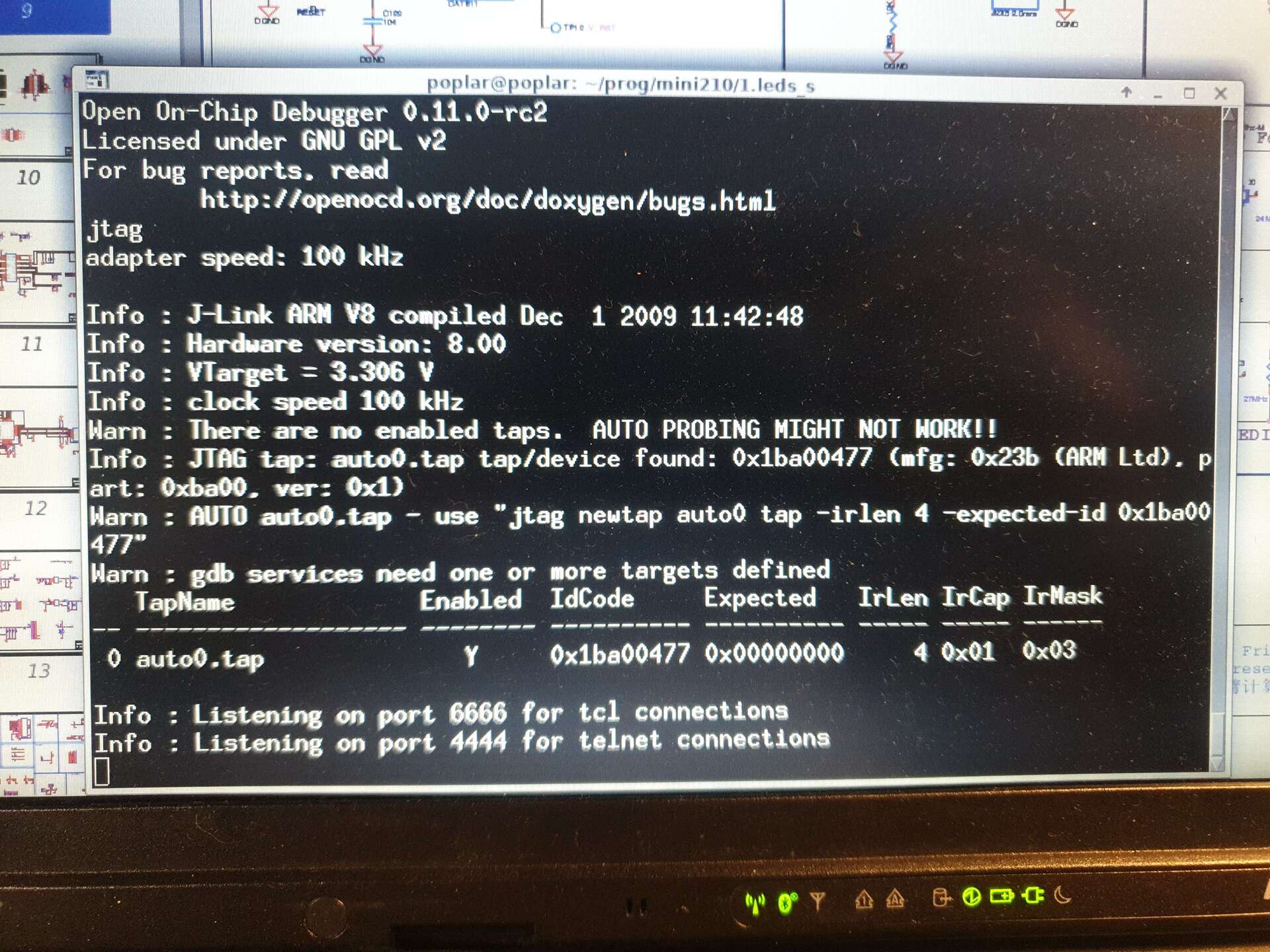
With help from the OpenOCD IRC channel I put together a configuration file which declared a Debug Access Port inside the microprocessor. I based it on the imx51 config file. After some trial and error OpenOCD detected the debug port. Fantastic! Now I was able to connect to it with gdb, control the code execution, set breakpoints and examine the memory contents of the chip. This was a very important step in the process.
The OpenOCD config file is quite short and simple. This is the target specific part, s5pv210.cfg:
if { [info exists CHIPNAME] } {
   set _CHIPNAME $CHIPNAME
} else {
   set _CHIPNAME s5pv210
}

# CoreSight Debug Access Port
if { [info exists DAP_TAPID] } {
   set _DAP_TAPID $DAP_TAPID
} else {
   set _DAP_TAPID 0x1ba00477
}

jtag newtap $_CHIPNAME cpu -irlen 4 -ircapture 0x1 -irmask 0xf \
        -expected-id $_DAP_TAPID

set _TARGETNAME $_CHIPNAME.cpu
dap create $_CHIPNAME.dap -chain-position $_CHIPNAME.cpu

target create $_TARGETNAME cortex_a -dap $_CHIPNAME.dap
There was only one problem with the JTAG - the S5PV210 seems to power down the JTAG peripherals when it's being reset. This causes OpenOCD to lose connection with the chip at the moment you reset it. It takes a while to re-establish the DAP connection and by that time the CPU has already executed the code you are debugging (and crashed). The solution to that is surprisingly simple.
The first piece of my code that the CPU runs is the BL1. So why not make the BL1 wait for me as I restart and reattach the debugger? I've modified the led blink example to put a single instruction at the beginning - an infinite loop. This way the CPU will wait there until I attach my debugger and use it to resume the execution on the next instruction. This trick is surprisingly useful if you can control the code that is executed, and have no breakpoint capability.
At that point I was experimenting with several different U-Boot trees, which caused some confusion, as one of them had a pre-compiled BL1 comitted into the source tree. I thought that it was a blob and tried to use it to load a BL2 of a different U-Boot fork... This was a dead end and it took me way too long to realize that the BL1 is actually compiled from U-Boot source code. It is quite confusing because U-Boot and Samsung call the different bootloaders different names. I will try to clear it up with this table:
| Bootloader stage | Filename | Samsung | U-Boot | function in U-Boot |
|---|---|---|---|---|
| stage 0 | (ROM) | BL0 / iROM | n/a | early init and load user bootloader |
| stage 1 | spl/u-boot-spl.bin | BL1 | Secondary Program Loader (SPL) | Initializes memory and loads proper U-Boot |
| stage 2 | u-boot.bin | BL2 | U-Boot proper | Initializes rest of the hardware and loads OS |
To put it to perspective of PC-class computers, stage 0 is the chipset ROM. It loads stage 1, the BIOS, from the BIOS flash. Then bios loads the MBR code, stage 2. And the MBR boot record loads the bootloader, which would make it stage 3. This is how the legacy ("BIOS") boot way works, UEFI is a bit different.
After figuring all this out, I built SourceLink U-Boot fork (at this point it seemed to be the most developed) and wrote it to SD card. I also studied the code of another fork for a long time to get an idea what exactly is happening in U-Boot's Secondary Program Loader (BL1 in Samsung speak) for this platform. That fork had a useful debug feature, it printed "Ok" before jumping to BL2/U-Boot proper. It is also programmed in a clever manner - the "O" is printed immediately after UART init, and "k" is printed after U-Boot proper is loaded into memory, just before the jump to it. This way when the code froze you know if it froze in BL1 or BL2.
I have also traced which UART is being set up - It turns out that this early debug message is printed on UART2, which is on CON3 on the mini210, and not on UART0, which is on CON1 and (as RS-232) on the DE-9 connector for the serial port.
I decided to re-use this idea and patched the fork I was working on to emit "O" early in the SPL, and "k" after U-Boot proper is loaded from the SD card. I uploaded the re-compiled SPL to the SD card, connected the UART adapter to CON3 and voila, i was greeted with an "Ok"!
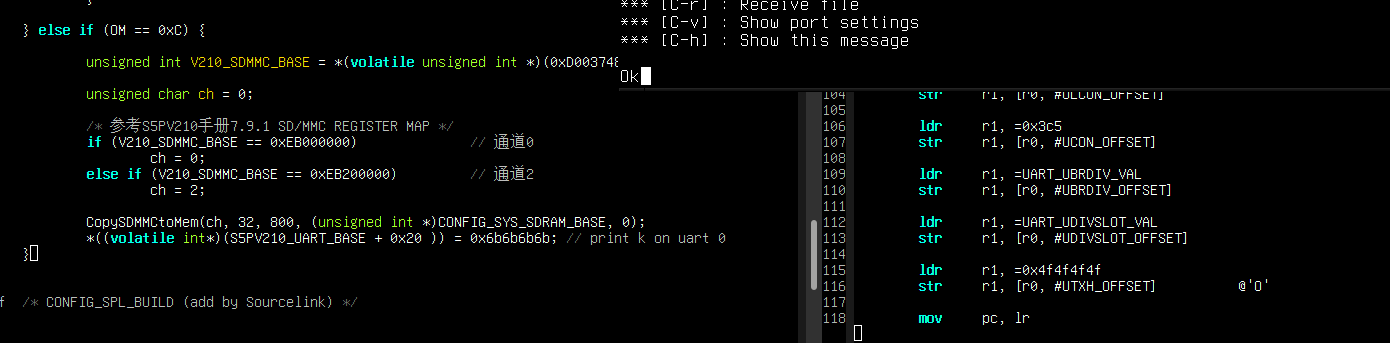
In the above image you can see a part of the terminal window with picocom (top) showing the "Ok" message, on the right, part of the ARM assembly code that initializes the UART and prints "O", and on the left, the end of a C procedure that loads U-boot proper from SD card. The last line is writing the ASCII value for "k" (0x6b) directly into the UART TX register.
At this point I confirmed that the SPL works. However for some reason it did not want to execute U-Boot proper (BL2). Throughout my debugging I have traced the execution of SPL until it's end. U-Boot's SPL only job is to initialize the memory controller (system RAM), copy U-Boot proper there and jump to the beginning of the loaded binary.
In my case that address was 0x20000000, but the memory there was empty. Tracing the execution took some time, as my debug setup still did not fully work. I was only limited to hardware breakpoints. I also did not have a proper "trace" ability. Usually, "tracing" the execution refers to entering a mode where the DAP itself records what instructions were executed and what jumps were taken, and then sends them to the debugger, which allows you to replay and rewind the program execution on your computer. In my case, "tracing" was done by single stepping the code and making notes. This way I confirmed the SPL is working as intented, that is:
Yet the place it was jumping to start U-Boot proper, was full of zeros. This in itself shoud not interfere, since the instruction 00000000 on ARM is equivalent to No-Operation (andeq r0, r0, r0), so it only advances the PC (program counter), but when I let it run, the debugger would indicate that, for some reason unknown at that time, the program crashed when executing an instruction before the system RAM (below 0x20000000). At that point I did not connect the dots as to what the real cause is, and came back to it after I fixed up the BL2.
At that point I put debugging BL1 aside, as I could load BL2 to the correct address over JTAG and debug it from there. That's what I did for a few days before deciding to tackle the first stage bootloader again.
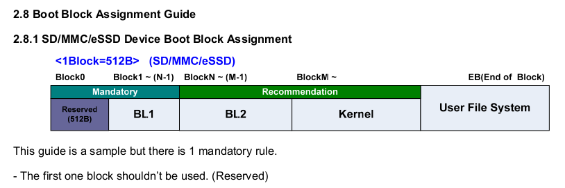
Coming back to troubleshooting BL1 I reiterated how the boot process works from the very beginning. My attention was caught by this diagram in the boot application note (screenshot below):
And this line of code in the procedure that copies BL2 to RAM:
CopySDMMCtoMem(ch, 32, 800, (unsigned int *)CONFIG_SYS_SDRAM_BASE, 0);
CopySDMMCtoMem is a macro which hides a less beautiful call to a raw function pointer
#define CopySDMMCtoMem(ch, sb, bs, dst, i) \
    (((unsigned char(*)(int, unsigned int, unsigned short, unsigned int*, unsigned char))\
    (*((unsigned int *)0xD0037F98)))(ch, sb, bs, dst, i))
It's C function declaration that uses a hardcoded function pointer. That's OK as at that adrress in ROM there indeed is a fuction with that signature. That's what the parameters mean:
ch is channel, (there are two SD/MMC controllers, 0 and 2), sb is starting block,bs is block count,dst is target ("destination")addressi controls whether to initialize the SD card (in case the BL2 is stored on a different SD/MMC than BL1).That function call copies 800 blocks (roughly 400kB) starting at block 32 (16kB offset) of the card to the configured SDRAM base address (RAM start). Reading the disassembly I confirmed that the target address and other parameters were allright.
You might ask why one would disassemble and read the code of an open source program, especially one that they have just compiled. The answer is pretty simple - U-Boot is such a large code base that it's sometimes easier to do it like this instead of attempting to try and follow which source file is linked in the final binary. While it's not impossible to do it analytically, one of the output build files is an ELF with debug information, which makes it easy to read. And besides that, machine code is what eventually gets loaded into the RAM and executed, so it never lies (at least not on CPUs as simple as this one).
The Sourcelink tree I was basing off has a script that prepares a full SD card image at the end of the makefile, so it prints the commands it runs. I can see how it assembles the full SD card image: First it takes the SPL, then it pads it to 16kB, then it appends the BL2 (U-Boot proper):
./tools/mksource210spl  spl/u-boot-spl.bin spl/smdkv210-spl.bin
cp ./spl/smdkv210-spl.bin ./tmp.bin
truncate ./tmp.bin -c -s 16K
cat ./u-boot.bin >> ./tmp.bin
mv ./tmp.bin ./u-boot-all.bin
And then I noticed how I image the SD card:
$ sudo dd if=u-boot-all.bin of=/dev/sdd seek=1 status=progress
Do you see the error? I write u-boot-all.bin starting at the first (not zeroth) block of the SD card, as per the boot ROM specification.. But the truncate command still pads the file to 16k (32 blocks). Which means that in the image, and on the card, BL2 is shifted one block forward. It is in fact at block 33. I checked that immediately - booted up the board, set a breakpoint at the end of BL1 and examined the memory at 512b into the RAM (0x20000200). Behold, I immediately noticed the 0xdeadbeef constant placed very close to U-Boot entry point.
> mdw 0x20000200 32
0x20000200: ea0000be e59ff014 e59ff014 e59ff014 e59ff014 e59ff014 e59ff014 e59ff014
0x20000220: 20000060 200000c0 20000120 20000180 200001e0 20000240 200002a0 deadbeef
0x20000240: 0badc0de e320f000 e320f000 e320f000 e320f000 e320f000 e320f000 e320f000
0x20000260: e51fd028 e58de000 e14fe000 e58de004 e3a0d013 e169f00d e1a0e00f e1b0f00e
That's where my BL2 was being loaded, offset by that one block!
I thought that my way of writing the bootloader to the card, which preserves the zeroth block, is correct. The first 512B are reserved by the ROM bootloader spec because that is where the master boot record of the FAT formatted card goes. This way you can have a FAT partition on the card that starts after the bootloader image, for use by the operating system.
I fixed up the truncate call in the Makefile to account for that 1 block offset, and after reflashing the card, the BL2 was loaded to the correct offset.
You could ask - if the problem was really one sector offset, and the first 512 bytes were filled with NOPs, why did the code crash? The CPU would go through the nops eventually and start executing BL2, right? Well, the answer is partially correct. BL2 is eventually executed, but at that point the program counter register is be wrong. Unlike BL1, it is not position independent code (PIC). BL1 is position independent because its common for it to be loaded into various addresses depending on the boot mode. Case in point, on the S5VP210, it's loaded with a header in all boot modes except emergency USB download mode, so in case of USB load it's loaded 16 bytes earlier into the iRAM. There are some cases when the bootloader is loaded into a known address - for example x86 BIOS is always loaded at ffff:0000, and boot sector code always starts at 0000:7c000.
Now it was time to troubleshoot the second stage bootloader. I've been doing this in parallel with debugging the first stage because I could load it over JTAG using OpenOCD command line:
> load_image u-boot.bin 0x20000000 bin
299548 bytes written at address 0x20000000
downloaded 299548 bytes in 110.032898s (2.659 KiB/s)
> mdw phys 0x20000000 32
0x20000000: ea0000be e59ff014 e59ff014 e59ff014 e59ff014 e59ff014 e59ff014 e59ff014
0x20000020: 20000060 200000c0 20000120 20000180 200001e0 20000240 200002a0 deadbeef
0x20000040: 0badc0de e320f000 e320f000 e320f000 e320f000 e320f000 e320f000 e320f000
0x20000060: e51fd028 e58de000 e14fe000 e58de004 e3a0d013 e169f00d e1a0e00f e1b0f00e
U-Boot has support for dual stage booting, which is used on this architecture. BL1, the Secondary Program Loader, loads BL2 (U-Boot proper) from the boot media and jumps to it.
During the build process the makefiles create a separate, small binary for the BL1 (SPL). The SPL is compiled after U-Boot proper.
Why is this important? Because of code reuse. There is a small subset of things that are common for BL1 and BL2, but are done slightly different. This is controlled by the macro CONFIG_SPL_BUILD during compilation.
For a while I was troubleshooting why U-Boot proper crashes early in it's code with a protection fault. After looking at the code for long enough I've noticed that both the SPL and BL2 contain a part that initializes Coprocessor 15. On ARM, this coprocessor implements the Memory Management Unit and a few other things. This is of course an error, since it should be initialized only once after boot. The CP15 init code is skipped if CONFIG_SPL_BUILD is not set.
After looking at the verbose compilation logs, I noticed that start.o file is reused. start.o comes from start.S, low level init routines written in ARM assembly. Turns out that my copy of U-Boot did not rebuild the assembly file despite building the SPL with different options. I've patched up the Makefile to force rebuilding of the start.S file every time and finally, the second stage had correct code.
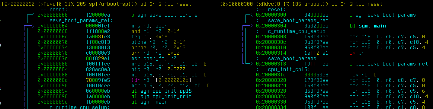
In this screenshot I have both BL2 (right) and BL1 (left) visible, showing that the start.S was indeed compiled twice with different settings. You can see that the SPL build has a bl sym.cpu_init_cp15 instruction, which is a function call to the function that initializes Coprocessor 15. The code of that function is also present in the BL2 code on the right (it's that bunch of instructions that start with mcr p15), but it's never called.
At this point I had fixed the bug with double initialization of the CP15. I began the slow process of putting breakpoints deeper and deeper into the code and single-stepping the instructions to see where the error appears. Once I verified that the next part of the code is reached, I noted that down and then the next restart I set a breakpoint there and single stepped on from that point. That way I've traced through the entire early U-Boot setup up until relocation stage. U-Boot Proper (BL2) early setup call tree looks more less like this:
reset:            // arch/arm/cpu/armv7/start.S, This is the entry point
_main:            // arch/arm/lib/crt0.S, initializes the C runtime (crt) - mainly sets stack pointer.
  board_init_f()  //common/board_f.c, At this point it's C code
    initcall_run_list(init_sequence_f)   // in lib/initcall.c
The initcall_run_list function is a clever trick which runs a bunch of functions one after another. init_sequence_f is a function pointer array -
typedef int (*init_fnc_t)(void); - and a for loop iterates over it until it encounters a NULL. The list of them is in common/board_f.c:847. The last function in that list is setup_reloc. It's worth to note that at this point if a function on that list fails, initcall_run_list returns false and the board will jump to a function called hang(). This means the stack trace does not contain the offending initcall function.
To my surprise the entire list ran ok. The code then returns to _main and begins the relocation.
In U-Boot, the relocation is necesary for a few reasons, but on this platform the most important one is that BL1 does not know the memory layout of the target U-Boot setup. Precisely speaking, BL1 only initializes the memory controller to make memory working - but the detection of available memory size is done by one of the function on the initcall list. This is why BL1 loads BL2 into the very beginning of the RAM, because there always will be working memory there, and after that BL2 checks how much memory is available and moves to the end of it. Of course BL1 could detect the ram size but it needs to be kept small and failproof, and the key to that is keeping it simple.
Next I looked at the relocation function, relocate_code (arch/arm/lib/relocate.S).
I glanced over it and started single stepping it. It did not look out of the ordinary - loads two addresses into a pair of registers...
ENTRY(relocate_code)
    ldr r1, =__image_copy_start /* r1 <- SRC &__image_copy_start */
    subs    r4, r0, r1          /* r4 <- relocation offset */
    beq relocate_done           /* skip relocation */
    ldr r2, =__image_copy_end   /* r2 <- SRC &__image_copy_end */
... then copies the data between them in a loop. And then I noticed this bit of code in the copy loop:
copy_loop:
@   b copy_loop                 /* commented out by polprog */
    ldmia   r1!, {r10-r11}      /* copy from source address [r1]    */
    stmia   r0!, {r10-r11}      /* copy to   target address [r0]    */
    cmp r1, r2                  /* until source end address [r2]    */
    blo copy_loop
The copy_loop routine has an infinite loop in it! This is not right... And it hit me - this is why the board freezes. At this point I became too tired of looking at the assembly and decided to take some sleep.
During the next day I did mostly some source code analysis to find out how the __image_copy_start and __image_copy_end macros are calculated. By tracing the macros doing maths on other macros and constants set by the linker, I finally arrived at these three macros in the board config header:
in include/configs/smdkv210.h:
#define CONFIG_SYS_SDRAM_BASE       0x20000000  /* modif by Sourcelink */
#define CONFIG_SYS_LOAD_ADDR        CONFIG_SYS_SDRAM_BASE + 0x40000000      /* modied by Sourcelink */
#define CONFIG_SYS_INIT_SP_ADDR     CONFIG_SYS_LOAD_ADDR        /* modied by Sourcelink */
That load address cannot be right... This board does not have RAM at that address. It merely has 512MiB of it. 512MB is 0x20000000 bytes. 0x40000000 is 1 GiB. There is no memory at 1GiB from the start of ram!
A useful constant to remember is that 1MiB is 0x100000. One meg is one hundred thousand in hex, as odd as it may be. I'm guessing by that macro the smdkv210 dev board has more than 1 GiB of RAM.
In order to test my idea the next day, I've stopped the code execution at 0x20000b38, which is the instruction that initializes the stack pointer,
ldr sp, =(CONFIG_SYS_INIT_SP_ADDR) ;; in crt0.S
And manually set the stack pointer to a sensible value. I chose 0x20100000 which is 1MB into the RAM. I figured that it should be enough stack space for the U-boot to continue with initialization. This was an educated guess and I had no idea how right I was - I set a breakpoint at 0x20000b78 (just before reloc) and resumed the execution.
It printed me the u-boot banner:
###############################
#### Ported by Sourcelink #######
#### Email: Sourcelink@126.com ##
###############################


U-Boot 2016.11 (Oct 08 2023 - 19:02:38 +0200) for SMDKV210

CPU : S5PV210@1000MHz
Model: Samsung SMDKV210 based on S5PV210
Board:  SMDKV210
DRAM:  1 GiB
That was the first time I saw the banner! I've then removed the infinite loop instruction in the relocation loop. At that point, after skipping past the SPL infinite loop (only thing that makes the debugger work for now) the board boots up successfully to command prompt:
Ok

###############################
#### Ported by Sourcelink #######
#### Email: Sourcelink@126.com ##
###############################


U-Boot 2016.11 (Oct 08 2023 - 20:12:13 +0200) for SMDKV210

CPU : S5PV210@1000MHz
Model: Samsung SMDKV210 based on S5PV210
Board:  SMDKV210
DRAM:  1 GiB
NAND:  1024 MiB
*** Warning - bad CRC, using default environment

In:    serial
Out:   serial
Err:   serial
Net:   dm9000
Warning: dm9000 (eth0) using random MAC address - 8a:31:8f:97:f2:e5

SMDKV210 # help
?       - alias for 'help'
base    - print or set address offset
bdinfo  - print Board Info structure
boot    - boot default, i.e., run 'bootcmd'
bootd   - boot default, i.e., run 'bootcmd'
Extremely happy that it finally worked, i've quickly patched up the CONFIG_SYS_LOAD_ADDR macro, recompiled and verified that it works without manual intervention!
Next day I made a fresh copy of that U-boot tree and exported all my changes into a separate board called mini210 with a config mini210_defconfig.
I've uploaded that source to github. It should create a working U-Boot for the FriendlyARM mini210 board: https://github.com/polprog/u-boot-mini210.
That's it. That's the last fix to get the board working! I have a working U-Boot!
Or is it? The next task is to build a working Linux kernel for it. But that's enough for this post. I've learned so much and there is so much more ahead. Thank you for reading, and stay tuned for more.