polprog, 29 march 2018
This text describes how to interface a computer running Linux, and by extention, most Unices, to microcontrollers over good old serial. I'll show and talk about code examples on both sides (both the microprocessor and the computer). Serial is one of the older but still widely used forms of inter-device communication. Once using bulky DB-25 connectors, nowadays most widely found as pin headers or test points on circuit boards of most devices, it is truly a magnificient protocol
Treat this as a form of a quick tutorial. You should know the basics of C and AVR programming. A led blinky, maybe some temperature sensor are a good start. Generally the more the better.
There are a lot of tutorials on AVR UART, and a lot about Linux serial programming. I couldn't find a decent one that explained how to connect those two things, so here it is. Enjoy.
We will put together and program a very simple mathematical coprocessor. It will be an ATmega8 that talks with a computer over a serial line. The computer will be running a terminal emulator for user input, and later, I will show you a way to script simple serial comms in Bash.
Our "coprocessor" will simply receive a string of characters representing a positive natural number and return it multiplied by 2. This way we can concentrate on the subject of making the whole thing work rather than writing complex processing code
Many types of serial interfaces exist. RS-232, SPI, I2C, UART - all of those are serial interfaces - and that list doesn't list the less common specialized ones. Usually, when people say "serial", they mean either RS-232 or USART, depending on the context. Those two mix very often with help of a handy chip called MAX232 - an RS-232 to USART converter. It's one of those chips every microcontroller lab should have in stock. We'll talk about it a tad later.
Nowadays RS-232 is less and less often found in computers. Cheap, fast and robust USB-UART converters took over. But the idea stays the same. Source code and information in this tutorial applies to those converters as well!
Those two interfaces have very much in common. In fact the only differrence between is in voltage levels. USART uses logic levels, so a 5V USART port will use 0V for 0 and 5V for 1. Similarly, a 3V3 USART will use 3.3V for a 1. RS-232 uses -15V and +15V respectively. Connecting RS-232 to a USART port will result in magic smoke coming out of the microcontroller, or the computer, or both. That's why we use a level shifter like MAX232.
The transmission of data in both is based on sending and receiving frames on two wires, RX and TX, receive and transmit, respectively. To make a link between two devices, you need to connect device A's RX to device B's TX and A's TX to B's RX. This is called a crossover [1]. A frame is a serie of bits: 1 start bit, 5-9 data bits (usually 8), an optional parity bit (usually no parity), 1-2 stop bits (usually 1).
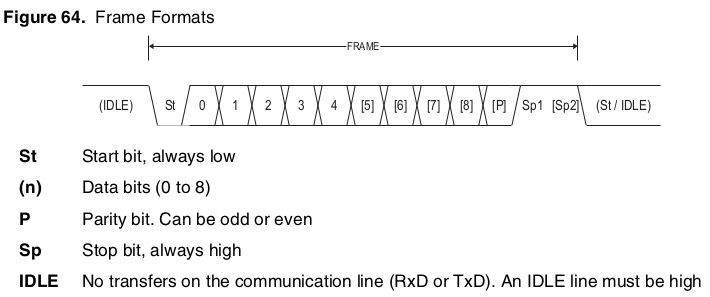
USART frame format (from ATmega8 datasheet)
As you may know, most microprocessors incorporate a serial peripheral. AVRs have a lot of them to choose from, and the most common is the USART. USART stands for Universal Synchronous/Asynchronous Receiver/Transmitter and as the name suggets it has a very wide variety of applications
Like most microcontrollers, the AVR uses IO registers to control its peripherals. An IO register is simply a defined address in the microcontroller's RAM, that a read or write triggers an action of the peripheral. This idea is as old as microcontrollers themselves, as I mentioned before. We will be programming in C, so, in fact, we dont need to know the exact adresses. We will include the <avr/io.h> C header that defines all the IO register and bit field (bit position names) for us.
There are two ways of implementing I/O operations. The first one is in blocking mode, where the program waits for an IO event (Received byte, etc.) to happen, stalling any operation. The other mode is non-blocking, where all the wait-prone IO operations are handled by the interrupt routines and the main program executes in the "spare" time.
The AVR will execute a very simple program. The main loop waits for a "data received" flag to be set, then reads a buffer, converts it to a number, does the math (multiplies it by two) and sends it back. We will implement the receiving part non-blocking, and the transmit part blocking.
The first thing you want to do is to set up UART's baudrate. A baudrate, or bps is basically the connection speed in bits per second. Its used to distinguish the bits per second in the physical medium (cable, radio, fiber) as opposed to connection speed (which you would use to talk about file transfer speeds [2]). Because UART is a simple protocol we can express the link speed as baudrate.
Two most common UART configurations are 9600 baud, 8 data bits, no parity, 1 stop bit (abbreviated as 9600 8N1), and 115200 8N1
AVR's USART peripheral has a 16 bit register (which is a pair of 8 bit registers), called UBRR. The name stands for USART Baudrate Register and it is the register the peripheral uses to generate the timing for the UART. The 8 bit registers are called UBRRL and UBRRH for the low and high byte of the UBRR register. The datasheet contains an equation for working out the correct value to put in that register, depending on your core clock speed. There are also some online calculators
Next task to do is to configure USART to our needs. We do this by setting certain bits in three USART configuration registers, UCSRA, UCSRB, and UCSRC. Those stand for USART Status/Control Register A, B, and C respectively. Lets take a look at the more important bits in each of them
In UCSRA there are four bit that are of our interest:
The next register, UCSRB, controls interrupts and state of the receiver and transmitter - important bits:
Register C - UCSRC - controls the frame length and parity checking of the UART
We can now write our uart_init() function:
      void uart_init(){
        // set baudrate to 9600 (U2X enabled, 1MHz clock)
        UBRR = 12
        // enable 2x speed mode
        UCSRA |= (1<<U2X);
        // Enable receiver, transmitter, and receive complete interrupt
        UCSRB = (1<<RXEN)|(1<<TXEN)|(1<<RXCIE);
        // Set frame format: 8data, 2stop bit
        UCSRC = (1<<URSEL)|(1<<USBS)|(3<<UCSZ0);
      }
And a function that will "print" a string to our uart:
      void uart_print(volatile uint8_t* message){
        while(*message){
          while(!(UCSRA & (1<<UDRE)));
          UDR = *message;
          message++;
        }
      }
Lets analyze it line-by-line:
void uart_print(volatile uint8_t* message){ defines a function called uart_print, it returns nothing and takes
an 8 bit integer pointer as a parameter. I'll talk about volatile in a moment.
while(*message){ loops as long as the dereferenced value of the pointer
(which is the value in the memory cell the pointer points at) is not zero. This with conjunction with
message++; (moving the pointer to the next character) stops the loop when it reaches the zero character
(null terminator - end of the string).
while(!(UCSRA & (1<<UDRE))); waits until the UART peripheral finishes transferring the frame. Then
UDR = *message; writes the current character to the USART Data Register, triggering it's transmission.
!(UCSRA & (1<<UDRE)) masks UCSRA with a mask that extracts the UDRE bit. This whole expression is then
negated so the loop runs as long as UDRE bit in UCSRA is zero.
Having previously enabled the receive interrupt we can write a handler. We need a buffer to hold our data in, an index to access it, and a flag to indicate that we received the data to be processed. Lets start by defining those three variables, and two macros, our delimeter and the buffer size
      #define DELIMETER 0x0D
      #define BUFSIZE (8)

      //we need a place to keep the incoming data and an index to access it
      volatile uint8_t buffer[BUFSIZE];
      volatile uint8_t idx;

      //flag indicating that a complete number was received
      volatile uint8_t process_flag = 0;
Notice that all three of our variables are defined as volatile. This is very important because of how interrupts work! Defining this volatile makes sure the compiler will compile code that reads the value from the memory (instead from a CPU register) every time it is read and writes it to the memory every time it is modified. This is called a read-modify-write cycle
Lets take a look at the interrupt handler:
	/*
	* Interrupt subroutine for UART receive interrupt.
	*/
	ISR(USART_RXC_vect){
 	  //store our character for further processing
	  uint8_t c = UDR;
	  if(process_flag != 0) return;  //do nothing if last data was not processed yet

	    //check if the character is our message delimeter
	    if(c == DELIMETER){
  	    buffer[idx] = 0;             //null terminate our string
	    process_flag = 1;            //flag that we need to process the data
	    idx = 0;                     //restore index to zero for next message
	  }else if(idx < BUFSIZE) {   //otherwise if there is space in the buffer, store it
	    buffer[idx] = c;             //write the character to the buffer
	    UDR = c;                     //echo the character back
	    idx++;                       //increment index
	  }
	}
Now we can write our main function. Let's start by including all the necesary headers for things we have used so far in the program
	#include <avr/io.h>
	#include <avr/interrupt.h>
	#include <stdint.h>
	#include <stdlib.h>
Two first headers are pretty straightforward - io.h for IO register definitions and interrupt.h
for the ISR() macro. Then
stdint.h
so we can use explicit types (like uint8_t instead of int), and
stdlib.h
for the atol and ltoa functions we will use in main()
to convert between strings and numbers.
Lets write our main(). The main function in most (if not all) microcontroller programs has this structure:
	int main(){
	  setup();

	  while(1) { loop(); }
	}
Our main() could look like this:
int main(){
  //initialize GPIO
  gpio_init();
  //initialize UART
  uart_init();
  //initialize buffer
  for(idx = 0; idx < BUFSIZE; idx++){
    buffer[idx] = 0;
  }
  idx = 0;

  //enable interrupts
  sei();
  uart_print("init ok\r\n");
  while(1){
    while(process_flag == 0); //wait for process flag to be 1

    // ( Magic happens here )

    process_flag = 0;
  }
}
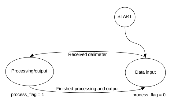
In the ISR we check and set a flag (process_flag). We can treat that variable as a state indicator. Notice that when the flag is 0 the program is in this state:
We can describe those two states (controlled by the flag) as:
Let's modify the loop so the program actually does some work
	//define a variable to store the number (16 bit) and an output buffer
	uint16_t number;
	uint8_t output[BUFSIZE];

	while(1){
	  uart_print("wait\r\n");
	  while(process_flag == 0); //wait for process flag to be 1

	  number = atol(buffer);    //convert from input buffer to a number
	  number *= 2;              //perform operation on the number
	  ltoa(number, output, 10); //convert back

  	  uart_print("\n\rok\r\n");
	  uart_print(output);       //output the result
	  process_flag = 0;
	}
At this point you can test the program by running a terminal (like picocom) and pointing it to the correct
serial port and with the correct baudrate. When you power on the avr you should see the init ok message.
Type in a number and press Enter. You should see it multiplied
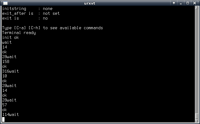
I entered 14. The microcontroller responded with ok and then 28. It works!
Our computer program, written in C, will use termios to interface the serial port. It will take a number as the input from a user, send it down the serial line to the AVR "math coprocessor", and read the result back.
Before that, we should remove the debug messages from the AVR program ("wait", "ok" messages and the serial echo). That way we can simplify the Linux program as it will not have to handle parsing those messages from real data. The AVR: main() will look like this:
      ISR(USART_RXC_vect){
	//store our character for further processing
	uint8_t c = UDR;
	if(process_flag != 0) return; //do nothing if last data was not processed yet

	//check if the character is our message delimeter
	if(c == DELIMETER){
	  buffer[idx] = 0; //null terminate our string
	  process_flag = 1; //flag that we need to process the data
	  idx = 0; //restore index to zero for next message
	  PORTB ^= 1; //debug
	}else if(idx < BUFSIZE) { //otherwise if there is space in the buffer store it
	  buffer[idx] = c; //write the character to the buffer
	  //UDR = c; //echo the character back
	  idx++; //increment index
	}
      }

      //...

      int main(){
        //...
        uint16_t number;
        uint8_t output[BUFSIZE];
        while(1){
          while(process_flag == 0); //wait for process flag to be 1

          number = atol(buffer); //convert from input buffer to a number
          number *= 2; //perform operation on the number
          ltoa(number, output, 10); //convert back

          uart_print(output); //output the result
          uart_print("\n");
          process_flag = 0;
        }
      }
With that out of the way we can start to write the serial handling code for the computer. Let's start with opening and configuring the port
#include <termios.h>
#include <stdbool.h>
#include <stdio.h>

#include "util.h"


int main(int argc, char** argv){

  if (argc < 2) {
    printf("Usage: %s <port>\n", argv[0]);
    exit(1);
  }


  struct termios options; //serial port options

  printf("Initializing serial port: 9600 8n1\n");
  //initialize serial port

  int portfd = open_port(argv[1]);
  tcgetattr(portfd, &options);
  cfsetispeed(&options, B9600);
  cfsetospeed(&options, B9600);

  options.c_cflag &= ~CRTSCTS; //no hw flow control
  options.c_cflag &= ~PARENB;
  options.c_cflag &= ~CSTOPB;
  options.c_cflag &= ~CSIZE; /* Mask the character size bits */
  options.c_cflag |= CS8;    /* Select 8 data bits */
  options.c_cflag |= (CLOCAL | CREAD);
  options.c_lflag &= ~(ICANON | ECHO | ECHOE | ISIG); //raw input
  //fcntl(portfd, F_SETFL, FNDELAY); //enable blocking
  tcsetattr(portfd, TCSANOW, &options);

  printf("Port attributes set\n");

  // ( Magic happens here )

  return 0;
}
That will be our base program. Lets recall how UNIX handles IO devices first, though
UNIX introduced the "everything is a file" concept. That means all our read and write operations on the serial port will be done using the read() and write() system calls. This makes it very easy to interface devices in *nix based systems since you use the same functions for receiving and sending data with all of them. Of course serial port is more complicated than a plain file on a disk, from the operating system view. That's why UNIX has a handy function called ioctl(), which controls IO devices. To simplify our program even more we will use Termios, newer API for interfacing serial on UNIX systems.
Lets analyze the above example of code
Starting from the top we have three includes:
termios.h for termios itself,
stdio.h for basic io functions (printf(), scanf())
Local header util.h
The last one is the most important. Its a set of conveinience functions i have written. One of those is already used -
open_port(). Lets take a look at it:
      int open_port(char *devname){
        int fd;
        fd = open(devname, O_RDWR | O_NOCTTY | O_NDELAY); //open rw, not a controlling terminal, ignore DCD
        if(fd < 0){
          fprintf(stderr, "Cannot open %s: %s\n", devname, strerror(errno));
          return fd;
        }
        return fd;
      }
And the includes in util.h look like this:
#include <stdio.h>   /* Standard input/output definitions */
#include <string.h>  /* String function definitions */
#include <unistd.h>  /* UNIX standard function definitions */
#include <fcntl.h>   /* File control definitions */
#include <errno.h>   /* Error number definitions */
#include <termios.h> /* POSIX terminal control definitions */
#include <stdlib.h>
#include <stdbool.h>
#include <sys/ioctl.h>
Before we write the rest of our computer main(), let's define a couple more functions to ease the programming:
bool write_chars(int fd, char *data){
  printf("Writing %s; len=%d\n", data, strlen(data));
  int status = write(fd, data, strlen(data));
  printf("Written %s; len=%d\n", data, strlen(data));
  if(status < 0){
    fprintf(stderr, "Cannot write data to port: %s\n", strerror(errno));
    return false;
  }
  return true;
}

char *read_line(int fd, char *buf){
  int pos = 0;
  while(true){
    int status = read(fd, buf+pos, 1);
    if(status == -1) {
      if(errno == EAGAIN || errno == EWOULDBLOCK){
	//End of data
	*(buf+pos) = 0; //Null terminate the string
	break;
      }else{
	fprintf(stderr, "Error while reading: %s\n", strerror(errno));
	break;
      }
    }
    if(*(buf+pos) == '\n') {
      //Received end of line
      *(buf+pos) = 0; //Null terminate the string
      break;
    }
    pos++;
  }
  return buf;
}
The write_chars() function simply takes a null terminated string, attempts to write it and returns a boolean status
depending on the outcome. Its a typical write() invocation. In case of a failed write it prints to stderr as well.
The second function on the other hand is a bit more sophisticated. It reads the input data character by character and checks for a newline. Its a very handy function when you need something higher-level than read().
Let's take the following code
  char *input, *output;
  input = malloc(16);
  output = malloc(16);
  scanf("%s", input);
  write_chars(portfd, input);
  write_chars(portfd, "\r");
  tcdrain(portfd);
  usleep(10000);
  read_line(portfd, output);
  printf("AVR returned: %s\n", output);

  free(input);
  free(output);
First we define two char pointers and allocate an input and an output buffer, both 16 bytes in size.
       char *input, *output;
       input = malloc(16);
       output = malloc(16);
Then the program reads a string from standard input and writes it, followed by a carriage return (our delimeter) to the serial port
	scanf("%s", input);
	write_chars(portfd, input);
	write_chars(portfd, "\r");
Next there are two function calls: tcdrain() and usleep(). This is the important bit.
tcdrain is very useful as it waits until all the data has been physically sent.
This is very important, as without this call the system kernel would just dump the data into the SuperIO chip (a chip on a computer motherboard that provides, among other IO, serial ports) buffer, and happily continue execution - immediately trying to read the input buffer, before the device on the other end had a chance to finish receiving the data!. In the above example i have also incluced a usleep call to delay the program 10ms after it finished the transfer, as the AVR waits until the transfer is finished before it starts to process the data.
It is possible to interface our AVR via a shell as well. Look at this script:
	#!/bin/bash

	#Set device path from 1st argument
	TTY=$1

	#set the serial port speed
	stty -F $TTY 9600

	#map parent's stdout to file desc 4 and stdin to desc 3
	exec 4>&1
	exec 3>&0

	echo "TTY is $TTY"

	# This subshell's file descriptors 0 and 1 will be $TTY but 4 will be parent's stdout and 3 parent's stdin
	# To echo to stdout we need to write to filedesc 4
	{
	  echo "Enter a number" >&4
	  read NUMBER <&3
	  echo "Sending $NUMBER" >&4
	  echo -ne "$NUMBER\r"
	  read  ANSWER
	  echo "AVR responded with $ANSWER" >&4
	} >$TTY <$TTY
	$ ./read.sh /dev/ttyS0
	TTY is /dev/ttyS0
	Enter a number
	412
	Sending 412
	AVR responded with 824
Below is a screenshot of oscilloscope traces of UART lines. The bottom one shows the data from the computer, and the top one is the AVR output.

This is a schematic of the hardware this guide was developed and tested on
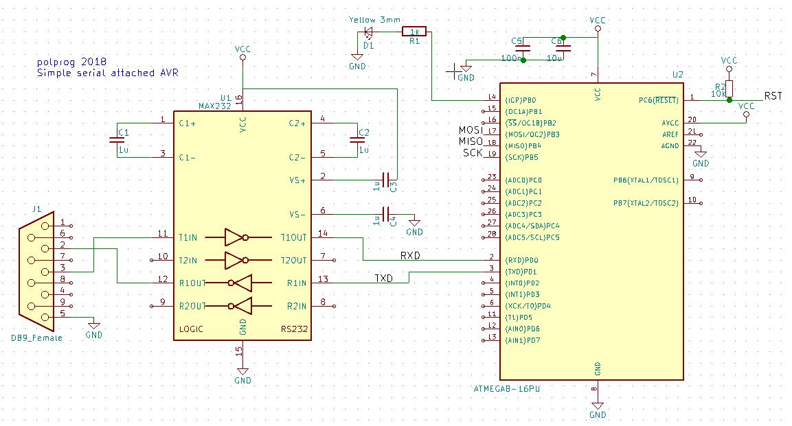
Source code and schematics are available as a .tar.gz here
It's possible that you will need to use sudo to access /dev/ttyS0 and other serial ports. The solution is to find out which group is the owner of the serial ports and add your user to that group
      $ ls -l /dev/tty*
      crw-rw---- 1 root dialout   4, 64 mar 28 23:50 /dev/ttyS0
      crw-rw---- 1 root dialout   4, 65 mar 28 16:54 /dev/ttyS1
      crw-rw---- 1 root dialout   4, 66 mar 28 16:54 /dev/ttyS2
      crw-rw---- 1 root dialout   4, 67 mar 28 16:54 /dev/ttyS3
      crw-rw---- 1 root dialout 188,  0 mar 28 23:57 /dev/ttyUSB0
In this case the group is dialout and it has read and write permissions to the ports. A simple
$ sudo usermod -aG dialout [username]
then logging out and in fixed the issue. I also had a USB-UART conevrter plugged in (shows up as /dev/ttyUSB0)
I hope you enjoyed this adventure into electronics and programming. My name is polprog and I can be reached at the freenode IRC network in #avrs or #polprog. Tell me if you want to add something here or suggest improvements! Have fun!
1 - That means USART is a point to point protocol, only two devices can talk to each other on one USART. Take a look at multi-device busses like SPI, I2C, or RS-485 (the last one being a half duplex, differential and generally very nice bus. It can be implemented with minimal external hardware using existing USART or RS-232 port)
2 - A higher level protocol, for example TCP, will add its own data to your data packets. Therefore if you transfer 100 kilobytes over TCP, the cable will in fact transfer much more data, which will be added and removed where its needed