polprog 13.03.2020
17.03.2020 (worked out and added maths for picking
the resistor). still being updated, stay tuned
Thyristor relaxation oscillators
Interesting and flexible circuit with a small component count
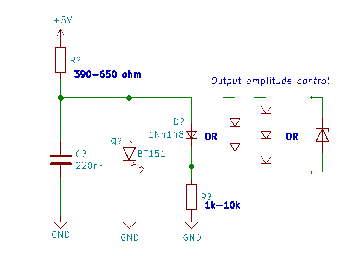
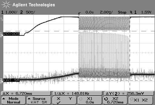
General schematic. Values given for BT151. Left - waveform with 2 diodes in
I've been playing with these little thyristor oscillators recently and came
up with some designs. Above there is a schematic for one variation of a family
of interesting oscillators.
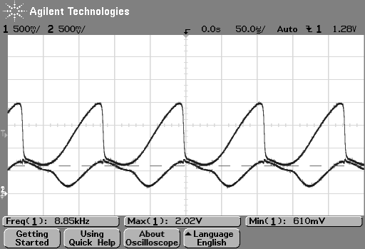
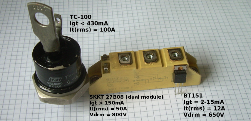
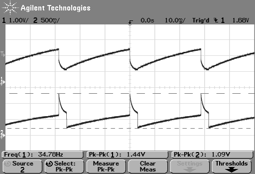
The smallest thyristor I could get is BT151, rated for 12A, 650V. On the scope traces
on this page, channel 1 is connected to the anode (shows cap voltage), and channel 2 to
the gate. All traces are from the BT151 circuit as picured above, left.
Thyristors (sometimes called Silicon Controller Rectifiers - SCRs) are very handy
semiconductor devices. Like BJTs, they are current controlled. If the current going
through the gate reaches a certain threshold of a trigger current (Igt), the thyristor
will start conducting. Once triggered it will keep conducting, until the current flow is
smaller than the holding current. You can think of it like a transistor with memory.
While these are mostly used in high-power electronics, their properties allow us to build
some interesting oscillator circuits.
So how does this work?
In this oscillator, the resistor charges the cap. The cap voltage also triggers the SCR.
If you pick the resistor right, once the cap voltage is enough,
thyristor will trigger, discharging the capacitor until about 600mV (1 PN junction drop),
and then shut off due to insufficient current, allowing the resistor to charge the cap
again. And the cycle will continue.
This oscillator can go into the 10kHz range (C ~ 220nF) or 10Hz range
(C ~ 200uF).
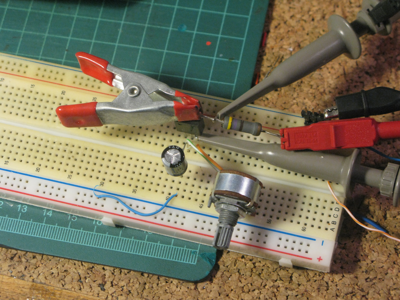
Initial version with a potentiometer between the gate and the anode. Later replaced
with a diode drop
Picking the right resistor
The frequency of the circuit is directly dependent on the anode resistor and the
capacitor.
With some luck and a scope or a DMM you can pick resistors at random and count that one
you picked hit the sweet spot.
Sometimes the oscillator will not work. This has mostly to do with the trigger and
holding currents of the thyristor. The rule of thumb for picking the anode resistor is:
- The resistor must be small enough to pass current to trigger the gate,
- but also big enough to not feed a current higher than the
holding current when the capacitor is fully charged
The cap should be big enough to trigger the thyristor. 220nF is close to the
low limit. Small signal thyristors could likely oscillate at higher frequencies.
The resistor on the gate doesn't change the frequency very much. In fact it might not
even be necesary. If you keep it, then at 12kHz, the
difference between 1k and 10k gate resistor is less than 50Hz.
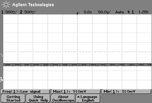
You can tell if you've over- or underestimated the resistance value by looking at the
voltages on the anode and gate.
- If the gate and anode voltages are very close (different by about 200mV max), the
SCR is stuck on. Too small resistance value keeps the holding current.
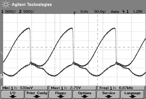
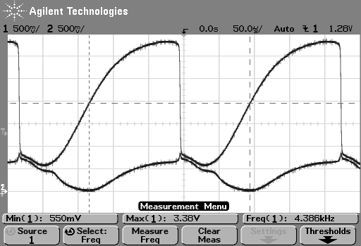
Left screenshot
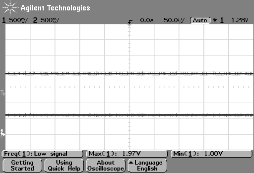
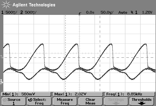
- If the anode is considerably higher than the gate, the resistor is too big, not
allowing enough current to trigger. Right screenshot
- If you can see it oscillate, it works. Duh. Middle screenshot
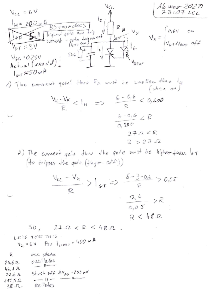
Calculating the right resistor
Maths to pick the anode resistor are below
In general, the resistance range depends on the voltage drop you force in series with
the gate and the trigger to holding current ratio. The values below are for the Semikron
power SCR module.
Putting the two conditions from above we can work out the maths. I've designated the
anode voltage as Vx, as that voltage is of particular intrest.
It directly depends on the current going from Vcc into the circuit. So by knowing that
voltage (and the anode resistor) we know the exact current going in. Note that this
circuit model has got rid of the gate resistor.
When the thyristor is on, Vx is equal to 0.6V - typical PN junction drop.
We know that the current then must be smaller than IH so that the thyristor
turns off at some point. That way we know the minimum value for the resistor to be
R > (VCC-0.6V) / IH
When the thyristor is off, the minimum current necessary to trigger it is
IGT. That was reported to be above the holding current in the datasheet
but (at least for this one unit) it turned out to be lower (measured 50mA).
If IGT was
bigger than the holding current then this topology would not work at all.
In the off state, Vx is set by the gate trigger voltage and the drop
we force with the diode(s). This way we work out the maximum resistor value to be
R < (VCC-VGT-Vdrop) /
IGT
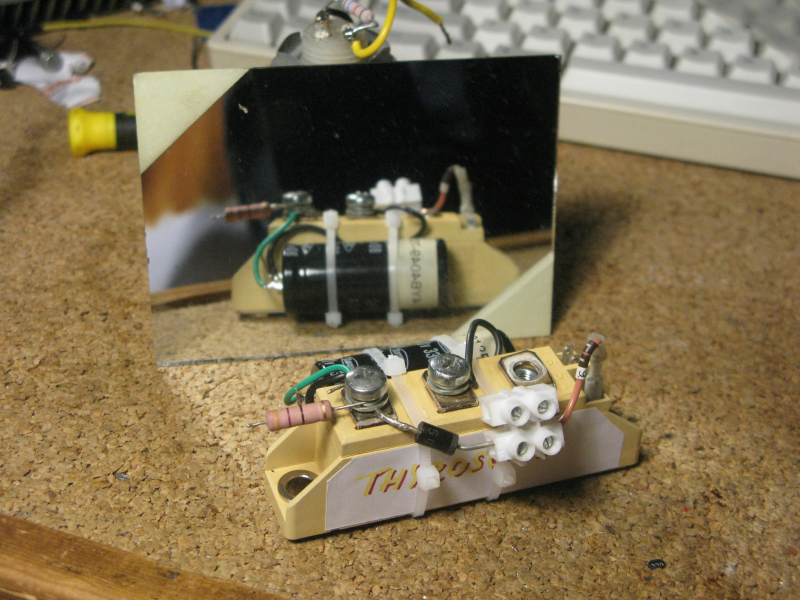
The oscillator built around a 3300uF cap and the SKKT 27B08 power SCR module
Put in the data for our thyristor and diodes, and we get R to be in range of 27 to
48 ohm. An important observation is that increasing the voltage drop (to increase the
amplitude) decreases the max resistor value!
The datasheet for BT151 specifies trigger current of typ 2mA and max 15mA.
This is a very broad range, so unless you
measure your part, you might have to do some guesswork (or math from the above) on the
anode resistor. Close enough values will make the oscillator ring for a bit then stop
like on the trace above. Depending on the anode and gate voltages after it stopped,
you can tell if the resistor is too big or too small. The BT151 I was using turned out
to be around 12mA Igt.
Gate diodes
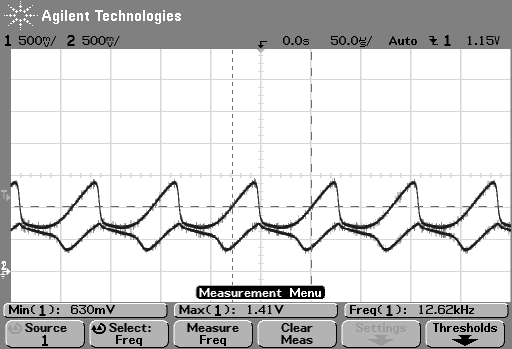
By adjusting the diode count you can adjust what voltage the capacitor charges up to until
the thyristor triggers. Left to right: 1, 2 and 3 1N4148 diodes in series.
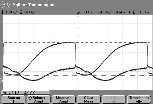
You can also do four, but thats kindof wasteful... Besides, this needs to have the supply
voltage cranked up to >=6V (left image)
For bigger drops it's wiser to use a zener diode. Here, a 3.5V zener (look at the
amplitude measurement) was used. Unfortunately, this one works on >6V only as well
(right image)
Frequency and resistor range
For BT151, cap value as above (220nF), and two diodes, the resistance values for the
anode resistor are in range of 390 to 600 ohms.
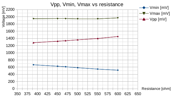
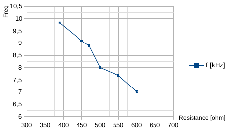
The diode count or type changes Vmax and frequency. The higher Vmax, the lower the
frequency at the same resistance.