Updated 2 may 2021 - added power supply section notes
Jump to: Introduction - Installing NetBSD - Hardware details - Power supply reverse engineering - Kernel woes - Kernel patching - Epilogue
The sky was clear and the concrete yard was filled with boxes and stalls full of odd electronic devices, ranging from great deals to absolute trash. While walking down an aisle between stall tents and plastic containers, a bunch of tiny devices with computer-like connectors, lying on one of the tables caught my attention. They seemed sturdily made and the seller had about 10 of them. I asked about the price and a moment later I was carrying five of them, having paid an equivalent of $6. I had no idea what to use them for, but I knew I they could be used for something...
This post is mostly my notes from messing around with this AMD/NSC Geode based thin client.
I have tried to boot some operating systems, in the end installed NetBSD/i386 8.0. I was able to run FreeDOS, Linux 2.4 and OpenBSD on it.
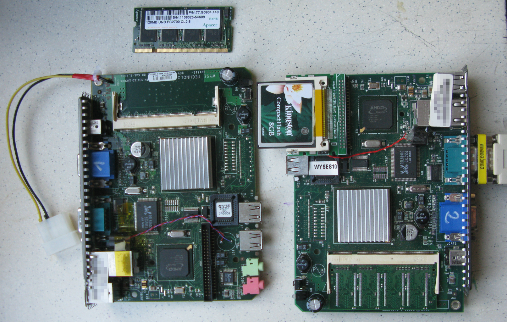
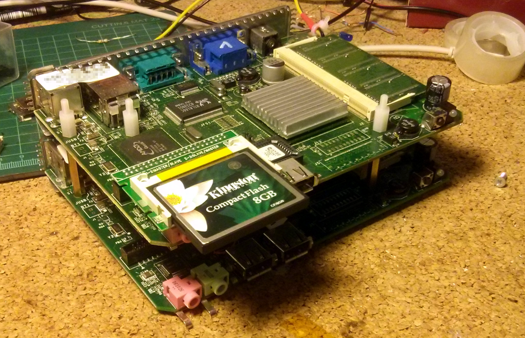
Winterm S10 board revision A1. They are stackable with standoffs!
Some time ago I made a video about booting linux with loadlin and DOS on them, I was booting that on the newer revision B4. That revision refuses to boot any medium bigger than 2GB
Winterm s10 is a WYSE thin client. Internally runs a custom operating system that looks and feels like a Windows-based thing. It has an AMD Geode 366Mhz CPU and my units came with a 128MB 2.5V 333Mhz DDR1 SO-DIMM ram stick.
I have five of them, 3 have a gray chassis and 2 white. The gray chassis ones have the A1 board revision in them and the white ones, revision B4. Bios in both rev A1 board and rev B4 board that I have been playing with is version 1.14, build date 04/23/2006.
Winterm s10 can boot of a usb-sdcard reader, revision A1 boots media without problems, revision B4 seems to ignore media bigger than 2GiB.
Both revisions of the motherboard feature a 44 pin, 2.5'' IDE connector. I'm using an IDE to CF card converter that works fine. If you are using a right angle converter then you have to select one where the IDE key pin is faced to the edge of the PCB, as converters the other way around don't fit unless you remove the board from the chassis and desolder and attach the pc speaker with a pair of wires.
Booting my rev A1 board is quite weird as for some reason the system won't react to the power button being pressed, instead I connect the DC jack, wait for the orange led to go off and strike the Del key. This brings up the BIOS menu. BIOS password is "Fireport" and cannot be disabled, only changed. Maybe you can set it empty, did not try this.
The above problem can be solved by setting "Power Control: Always On", this way the unit starts whenever there is power connected.
NetBSD/i386 8.0 booted from a USB SD card reader. The image written to the SD card was the install.img file.
Using default options it hangs on a message about pckbc0. Disabling that device helps, to do that press 4 at boot menu and type "boot -c", this will drop you to userconf(4) after the kernel loads, where you disable the AT keyboard controller with "disable pckbc0". This allows you to boot the kernel and get into systinst(8). At first i went too far and disabled whole ISA bus but that caused the system to not see my CF card!
If you are disabling or otherwise need to edit boot options or userconf, the system has you covered as you can put the boot command line in /boot.cfg file. In my case the line is:
"userconf disable pckbc0; boot netbsd"
With pckbc0 disabled the system has successfully booted up and I was greeted by the white-on-blue menu of sysinst(8). Apart from that pckbc0 quirk, it is a typical NetBSD/i386 installation.
At first i messed up the partition scheme. Reinstalled it with a good partition scheme. Works
DC jumper
There is an unpopulated jumper on rev A1, designation JDC1. Its directly connected to the DC jack and can be used to provide 12VDC power to the board. Located top right, board oriented ports up, ram right. Designation is hidden under the ram stick. Pinout as follows: Upper pin (closer to mouting hole) - 12VDC, lower pin is GND.
I've soldered 12V and GND cables from a female molex connector, this way I'm able to power if off an ATX psu. It's a good idea to tie it to the mounting hole with a ziptie for strain relief :)
GPIO devices and other unpopulated connectors
The chipset chip U3, ("Companion device"), AMD Geode CS5536AD has some GPIO devices that NetBSD is able to pick up and assign /dev/gpio0 to this port.
Those do not seem to be broken out on any jumper on the board but board revision A1 has got a lot of vias under the chip and it should be possible to probe or connect a jumper wire to one of the vias. The silkscreen printing carries a very nice legend that helps identifying the correct ball. This chip is very interesting because it controls a bunch of low level stuff. Some of them include boot option select, and SMBus (G3 - CLK, F1 - I/O), and UART/IRDA 1 and 2
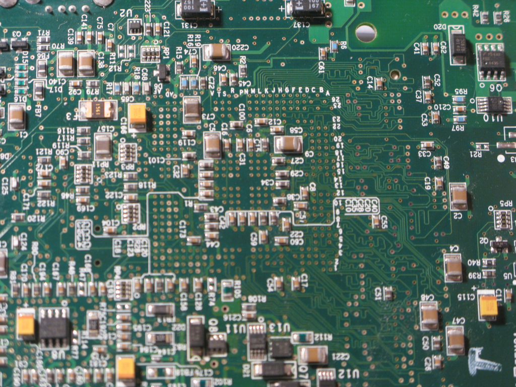
Due to this easy probing availability its a good board for driver development, you can easily probe and even attach additional SMBus (or the like) chips to it!
CS5536AD datasheet is available online, ball assignments page 25 onwards.
Other jumpers and interesting points include (board rev A1):
BT1 - Top pin connected to Vbat [A3], bottom to GND (board orientation the same as in point 1).
Vbat pin is described as "RTC battery". Chapter 7.1.4 of the datasheet shows voltage range from min 3.14 to max 3.46, typical 3.3 - according to the datasheet a simple CR2032 will not work!
JFS1 - some JTAG
rest of the jumpers unindentified. This is pretty difficult due to this being a multilayer board!
7 vias in a copper fill next to the big cap near power button, +Vin from the DC jack.
The serial interface is running on +/-9V, should work with everything.
Kiwa on twitter found out that their Wyse VX0 S30 boots fine when powered from 5V, so I decided to take mine out of the bag and check that too. When powered from 5V, my S10 will boot the internal OS fine.
Due to the cable resistance, the actual voltage at the input drops to about 4.86V, so a short cable should be used. This causes the USB port voltage to drop to that level too. The USB voltage cannot be connected direclty to the power input (that runs at 12V nominally) - it is generated from the buck converter. At Vin of about 5V the USB voltage buck converter keeps the mosftet conducting at all times. Here are duty cycles on the 5V buck's mosfet gate for different voltages:
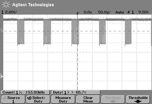
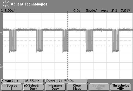
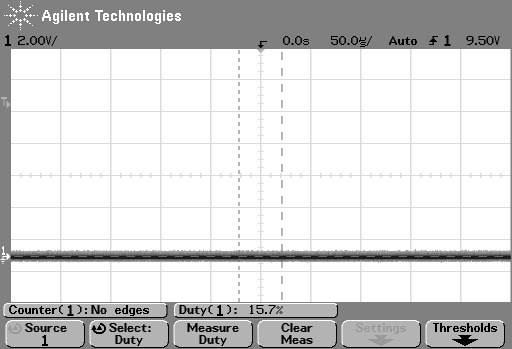 Buck converter PMOS gate duty cycle at Vin= 12V (1st trace), 9V (2nd trace), 5V (3rd trace). The MOSFET is a PMOS, so low = conducting. At 5V, the mosfet is open non-stop. Signal is active low, so the duty cycle measurement of the scope is inverted.
Another thing to keep in mind is that with lower voltage the input current increases. The buck will also have to work at a larger duty cycle. But throughout the time I was testing it, the client operated in a stable manner down to about 4.8V at the input.
The PSU topology is pretty simple. There are 4 voltages: 5V, 3v3, 2v5 and 1v5 necesary for the computer to work. There are three buck converters which make these from the input voltage. The buck converters are shown on the pictures below:
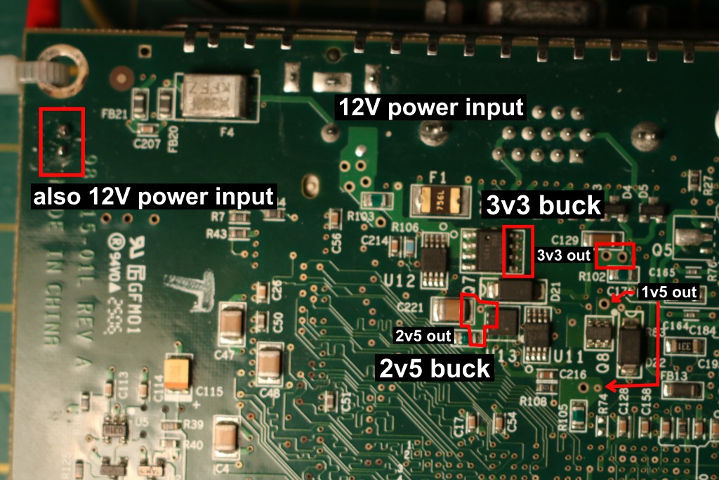
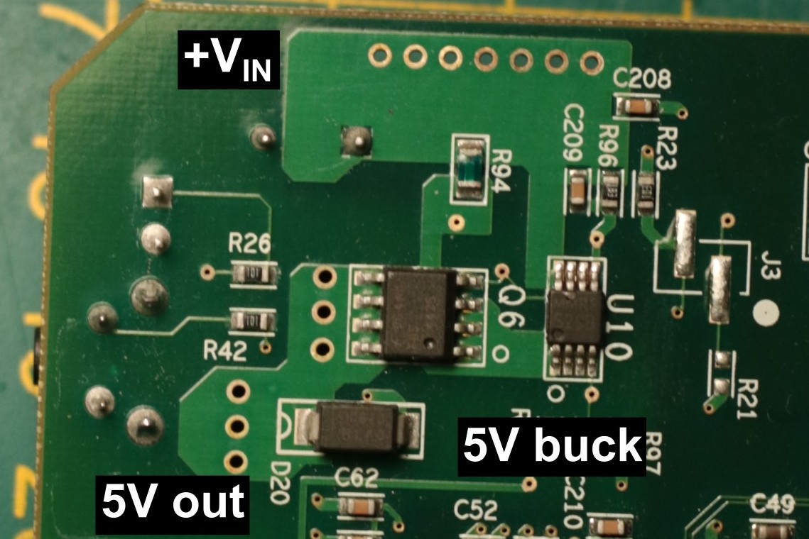
Location and topology of power supplies. Click to enlarge
The converter controllers are LM3485, marked S29B on the SMD package. They come in VSSOP8. Datasheet for the LM3485 gives the maximum input voltage as 35V, and it appears that the 12V is not conencted directly to anything but the buck cinverters. I was able to get the S10 running from 24V Vin, however the capacitors across the input voltage power rail are only rated for 25V. I would not recommend exceeding that rating, and even the 24V is a bit on the high side.
This means that the S10 can run at any voltage between 5V and 24V (in theory even 35V, if you replaced the capacitors). That includes any random laptop charger, as these are usually in the 19-21V range, or battery packs, which have a voltage that depends on the charge level.
Note that there are three converters but four voltages. The 1v5 rail is generated in a weird way by a OM7654SM regulator, which for some reason is labeled Q8. Four of it's pins are connected together (+VIN, -VADJ, +VADJ, +VOUT, that is pins 1, 2, 5, 6). Pin 3 (-VIN) goes to the gate control pin of U11 (the 2v5 buck) and pin 4 (-VOUT) goes to ground. I have no idea what is going on in there. The CPU would reset when I measured the 1v5 rail with a DMM, which can be expected
Even with 5V input, the serial interface is running on +/- 9V, it has it's own charge pump
I'm curious why the NetBSD kernel hangs on boot if pckbc0 is not disabled. The kernel boots fine if you compile it without pckbc, but that causes some other problems - like for example no keyboard until the kernel initializes the USB devices, which leaves you without the ability to type during that time.
When I first installed NetBSD on it I managed to screw up the partition table (on i386 partition C and D is whole NetBSD MBR partition and whole disk respectively). I could not reproduce that screwup. It might have been something to do with OpenBSD being installed previously on that (but when OpenBSD froze on it's kernel relink stage for 30 minutes (this is a 366MHz Geode and a slow IDE interface, remember?) i just yanked the power cord and installed NetBSD on it).
So far I've managed to find the exact bus_space_write_1 call that hangs the CPU!
The kernel hangs when trying to write a value to IO port 0x64, which is the PS/2 command register.
The CS5536AD Companion Devive emulates a PS/2 keyboard controller. It maps I/O port writes to the right MSRs (Model Specific Registers - special registers in x86 based CPUs available with rdmsr and wrmsr instructions, since Pentium). IO ports 60h and 64h are mapped to allow BIOS and such to interface with the emulated PS/2 keyboard "the old way".
Furthermore, the kernel also hangs when using the serial console (albeit while trying to write a different value - 0x60 for VGA console and 0xAA for serial console
It's been a month or more since I have given up on debugging this. I have decided to write about that I have found out (so far?)
I was browsing the datasheet of the CS5536AD, focusing on the keyboard controller
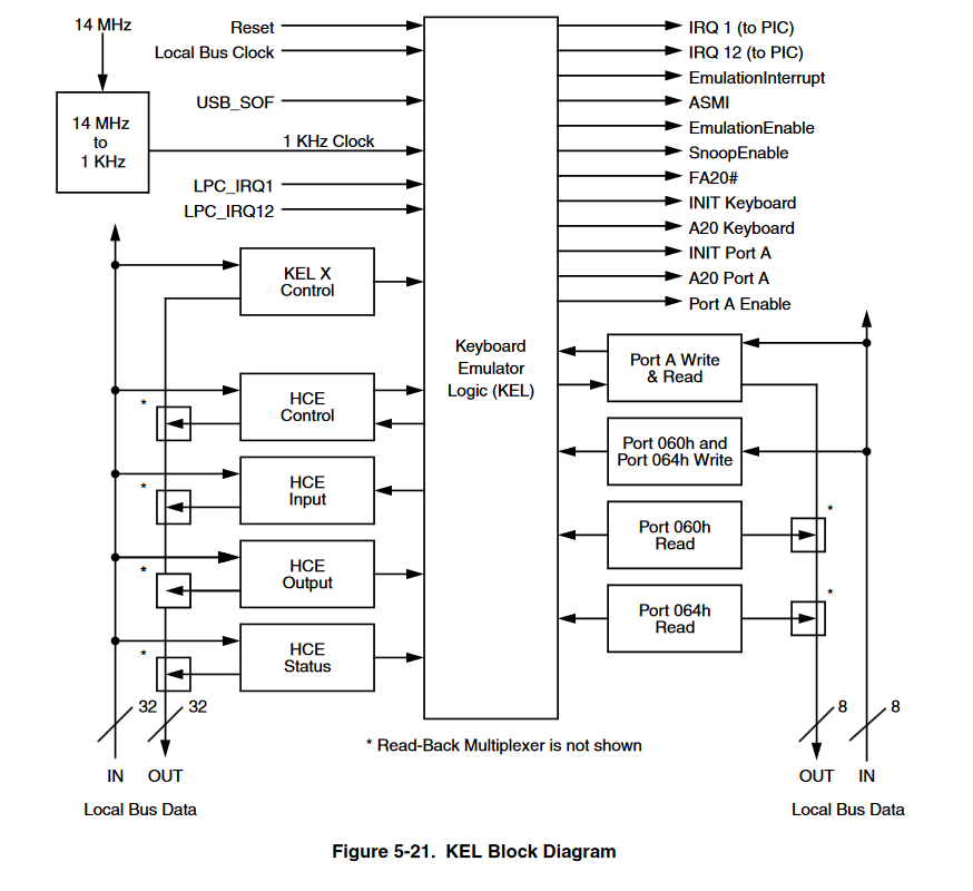
In the chapter 5.10.8 the so-called Force A20 Low Sequence is described:
The FA20 sequence occurs frequently in DOS applications.Mostly, the sequence is to set FA20 high; that is, do not force address bit 20 to a 0. High is the default state of this signal.[...]
The A20 sequence is initiated with a write of D1h to I/OAddress 064h.[...]
As mentioned above, a write to I/O Address 064h of any value other than D1h causes A20Sequence to be cleared. [...]
Luckily during my kernel debugging I have been taking pictures of what my printf invocations produced on the screen in the boot log.
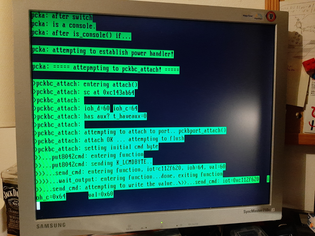
This is one of those images. The kernel is not paused here, nor an infinite loop was inserted. It froze - right after writing the value of 0x60 to port 64h. In fact it didnt even exit the send_cmd function, or for some other reason did not execute the next printfs.
What is more fascinating is that, having no other idea, I modified the function in a way that sends 0xD1 to port 64h after every write, like this:
      printf(">>>...send_cmd: writing the actual value...");
      bus_space_write_1(iot, ioh_c, 0, val);
      printf("okay...");
      printf("writing D1...");
      bus_space_write_1(iot, ioh_c, 0, 0xD1);
      printf("okay...\n");
      printf(">>>...send_cmd: ok, exiting function\n");
... and the kernel booted successfully to a shell!
Having restarted the computer a couple of times to check if that wasn't some crazy strike of luck I copied the compiled kernel binary to a regular PC running NetBSD and tried to boot it.
It failed. The computer reset just a moment after the bootloader loaded and executed the kernel.
It seems that either forcing the A20 address line low is making the kernel able to boot, which is extremely unlikely and there is no way a modern system kernel would boot with this address line foced low, or the companion device is misconfigured, wrong, there's an error in the datahseet or whatever else...
Whatever that was, disabling (enabling?) the A20 Sequence by sending 0xD1 after every byte makes the kernel boot successfully on the thin client. And on nothing else.
The keyboard controller topic is still open to discussion - is it really the fault of the chip or is it one of those bugs that are less clear the longer you stare at it?
If you are interested in the KBC issue you might find my mailing list messages useful:
First message
and the
second one
There is more information about the Sx0 series on the Parky Towers website The CS5536 datasheet is available here.