polprog 23.02.2020
Jump to: Etching, Small VCO Circuit
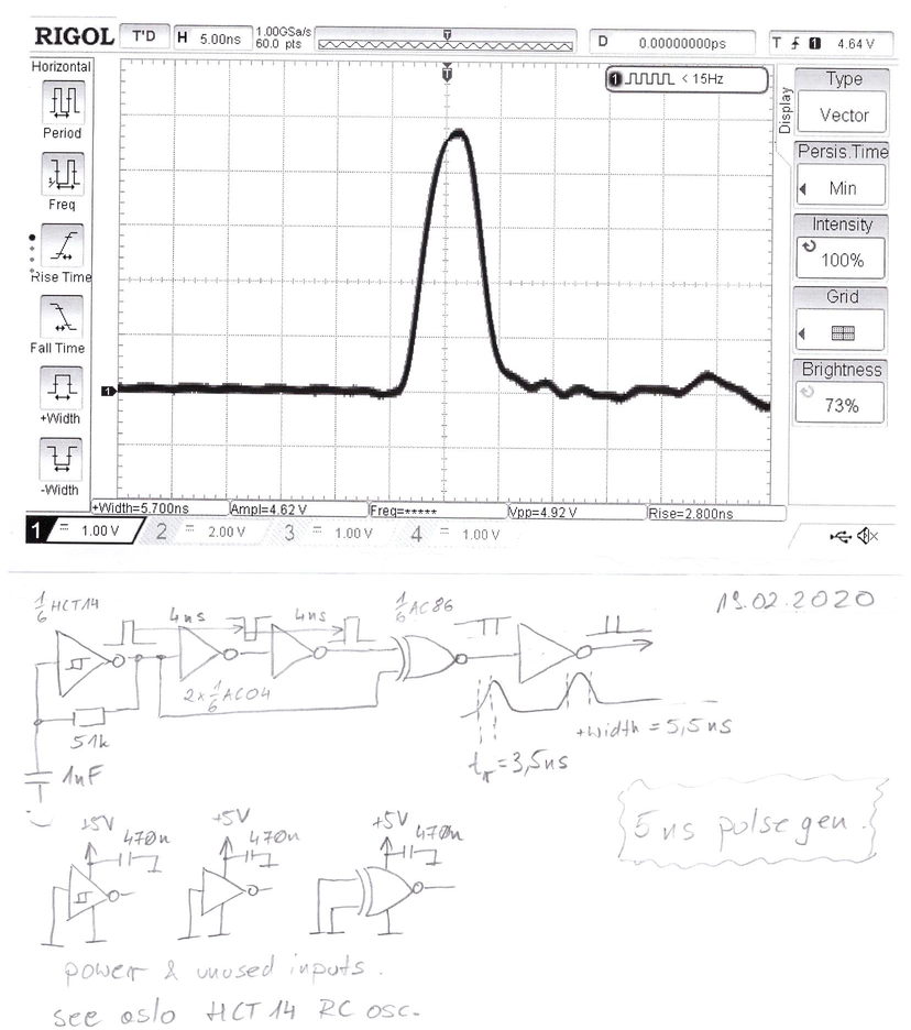
The cricuit above generates more-less 5ns wide pulses. It's very simple and easy to build.
The leftmost 74HCT14 is a simple relaxation osc. It generates pulses of some frequency and duty cycle. Then, the signal forks and is fed through to the 74AC86 XOR gate. One of the inputs of the XOR gate is connected directly to the output of the relaxation osc. The other input is also the oscillator signal, but fed through two 74AC04 inverters. This way it's the same polarity, but its skewed in time by 8 nanoseconds (my 74AC04 has a 4ns propagation delay. The datasheet specifes min. 1.5ns, max 6.5ns, typ 4.5 at Vcc=5V). Because of that, the XOR gate receives the same logic level on both inputs except for when the oscillator generates an edge on it's output. Then, the input logic levels for the XOR gate is different for about 8 ns, as thats how much time it takes for the edge to propagate.
The pulses come in pairs, as each pulse corresponds to an edge of the relaxation osc output. You can change the pair frequency by adjusting the frequency of the oscillator. If you need to have evenly-spaced edges, use a binary counter IC (such as CD4060, 74xx69, 74xx90, 74x92 etc.) to get a 50% duty cycle square wave (or feed one from a sig gen).
My circuit ran at 5V. Below is the scope trace from the schematic file on my Rigol 1054Z (50MHz, 1Gsa/s; Traces from other, faster oscillosopes are later in the page)

At these speeds, probing technique matters a lot! Regular hook-and-clip probes will not come in handy as the inductance of the ground lead is too high. Using the ground springs helps a bit, but there is still a better, simpler solution:
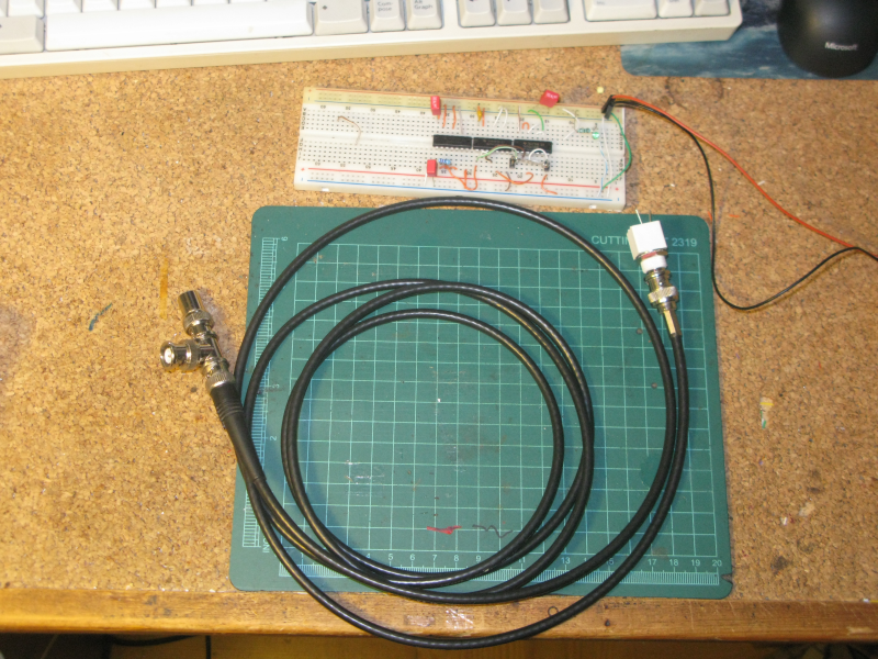
The high speed probe I've used to measure that signal is very easy to make and useful to keep in mind. A length of 50-ohm coax has got a male BNC socket connected on one end. On the other end there is a tee for scope connection and a 50-ohm terminator (the Rigol DS1054Z does not have a 50-ohm input option). If your scope has one, you don't need the tee at all. Note that this is a 1x probe. If you have your scope set to 50 ohm input impedance, and keep the tee, you get a 2x probe.
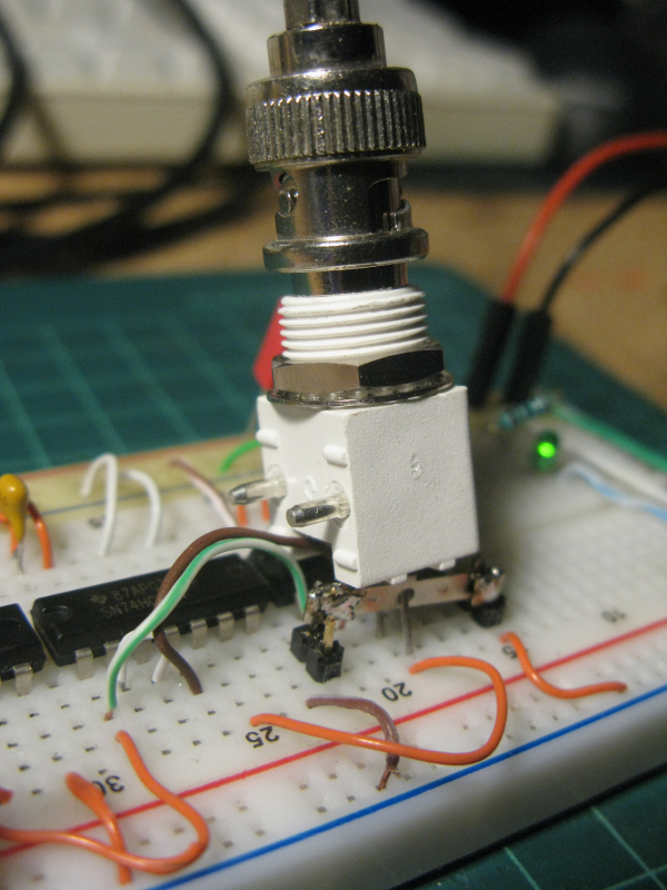
Connecting the probe to the breadboard. The metal strip goes to the IC's ground on one end. It's 100 mils longer than the DIP IC, so the other end is not connected. This way you can get a solid ground connection for various probes.
This probe is okay for probing CMOS outputs, as they can drive even a 30 ohm load. But, if you are trying to probe other signals, keep in mind this probe is a 50 ohm resistor to ground from the circuits point of view.
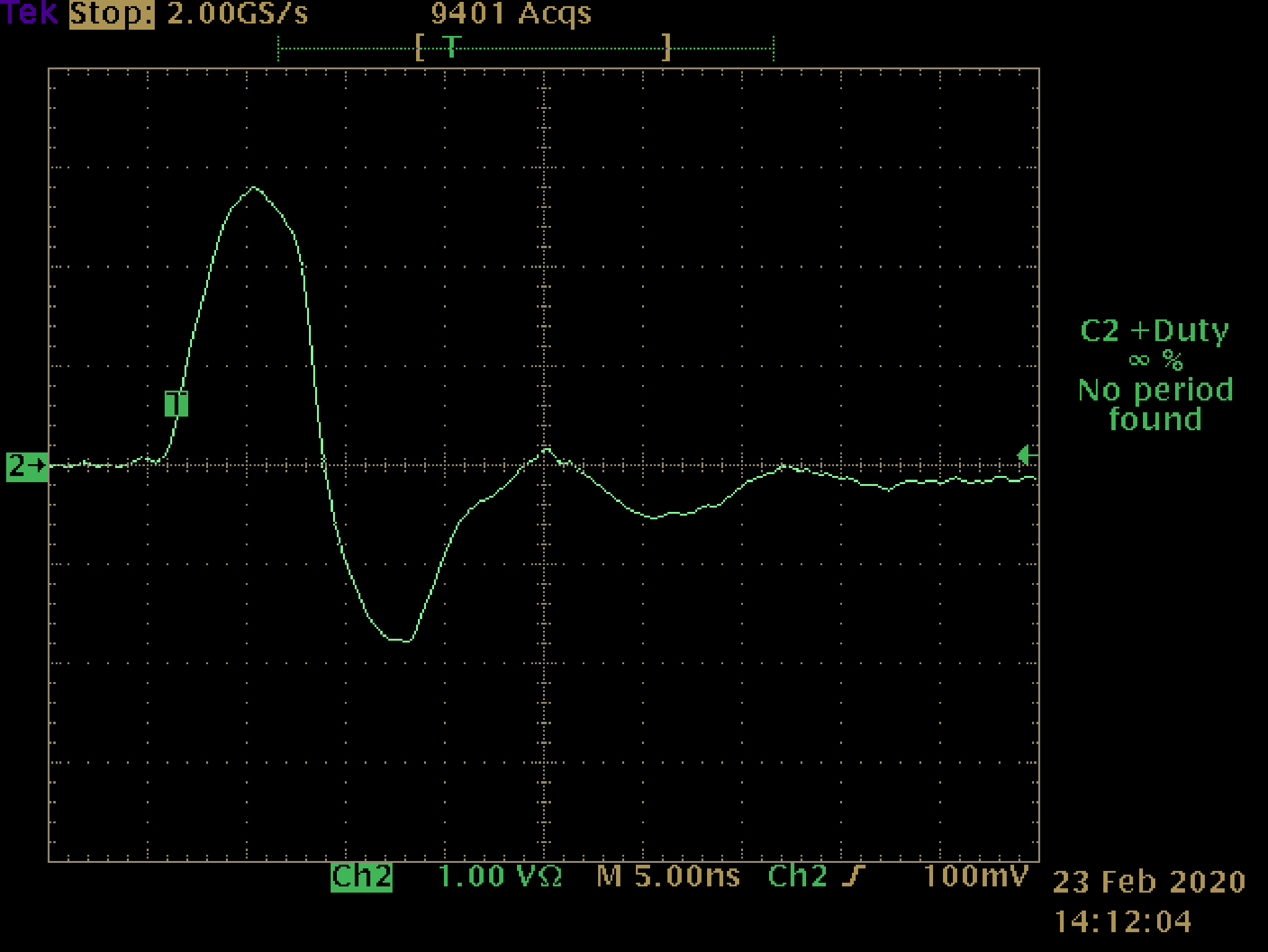
Above, output from the same circuit, but built with 74HC04 inverters and 74HC86 XOR [rue]. You can see how the pulse is barely 300mV in amplitude. Notice the negative echo just after the pulse, most likely related to various parasitic inductances or reflection in the signal path.
Other measurements of the HC series based circuit below [polprog]


Oddly enough there seem to be two different slew rates for a rising and a falling edge from the oscillator. The HC series is too slow to even reach the 5V level on the pulse. (pay attention to V/div on these screens). This could have something to do with the scope sample rate but I'm not sure. I'll have to test it in the next version.
Either way, the HC series is just too slow to evenbe considered usable for this project
01.03.2020
I've put together a small (3 x 9.5 cm) PCB that holds the circuit very similar to these shown above. However, there are two small differences. I've added a jumper that allows you to select between 2 or 4 inverters in chain (this way you can adjust the pulse width). The XOR gate is also directly driving the output because it's output polarity is different than the breadboard circuit, which was an oversight on my end when drawing the schematic of what's on the breadboard.
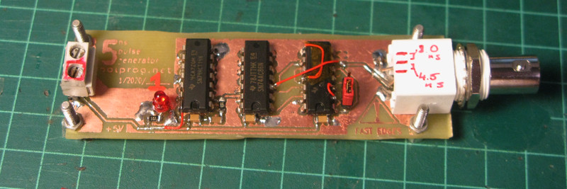
Etching the PCB was done with the toner transfer method using sodium persulfate.
Read more about etching or design choices
Because of lower stray capacitances and material differences, the PCB version of the generator is faster than the breadboard one, and can reach 4.5 ns pulse width. Cool!
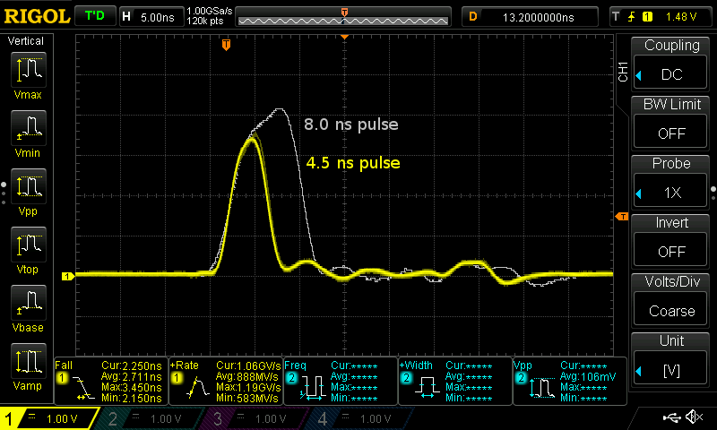
The Rigol traces are from 1054Z (50MHz 1Gsa/s). Below are two extra traces, from the same PCB in 4.5ns mode, as seen on different, faster oscilloscopes. Both scopes are 100MHz in bandwidth and both have an external (same) 50 ohm inline termination at the input.
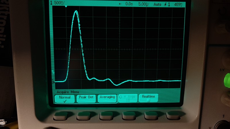
Agilent 54622D (100MHz, 200Msa/s, equivalent time sampling)
Notice that on the Agilent, the signal tail stabilizes 1 division earlier than on the other digital oscilloscope :-) Because it switches to equivalent time sampling at the fastest sweep speeds, it takes about 40 sec to get a full image.
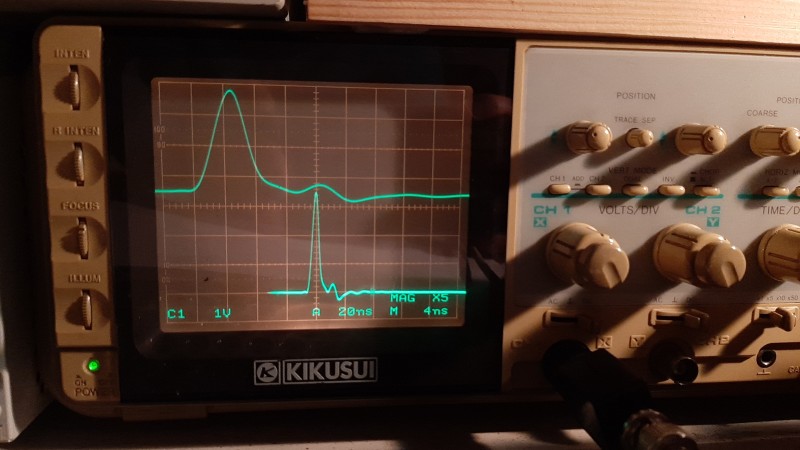
Kikusui COR55xxU (100MHz, 20ns/div, with 5x magnified trace on top at 4ns/div)
This VCO is very similar to the relaxation oscillator used above.
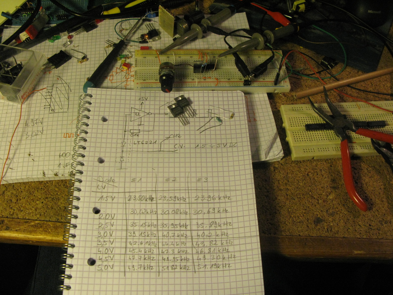
Instead of a capacitor, a dual diode in a TO-220 package is used like a varicap diode. The diodes were pulled from a dead ATX power supply (these are very useful part sources, by the way). In my case it was an LT6221.
By varying the voltage between the diodes, the width of the depletion region in the bottom diode varies. Higher voltages give lower capacitances, and respectively higher frequency (to a point, at about 15V the frequency starts falling again).
The control voltage (CV) range is wider than in the picture. In the end I've managed to get the frequency stable an adjustable within a 3.2:1 ratio, with the CV ranging from 1.5 to 15V.
General frequency chart for 1.5V - 5V range at R=51k
gnuplot plot.gnuplot > plot.svg
Additionally, the following R values give these ranges at C.V. in range of 1.5 to 5 volts
| 1k * | 1790 to 3310 kHz |
| 10k | 140 to 302 kHz |
| 51k | 23 to 49 kHz |
| 100k ** | 10.5 to 17 kHz |
* at 1k the frequency change is non-monotonic.
** at resistances higher than 100k the generator does not always start